Information injection-pump assembly
BOSCH
9 400 615 598
9400615598
ZEXEL
101607-1190
1016071190
MITSUBISHI
ME086626
me086626
Rating:
Service parts 101607-1190 INJECTION-PUMP ASSEMBLY:
1.
_
6.
COUPLING PLATE
7.
COUPLING PLATE
8.
_
9.
_
11.
Nozzle and Holder
ME086575
12.
Open Pre:MPa(Kqf/cm2)
17.7{180}
15.
NOZZLE SET
Cross reference number
BOSCH
9 400 615 598
9400615598
ZEXEL
101607-1190
1016071190
MITSUBISHI
ME086626
me086626
Zexel num
Bosch num
Firm num
Name
101607-1190
9 400 615 598
ME086626 MITSUBISHI
INJECTION-PUMP ASSEMBLY
6D31 K 14BE INJECTION PUMP ASSY PE6A PE
6D31 K 14BE INJECTION PUMP ASSY PE6A PE
Calibration Data:
Adjustment conditions
Test oil
1404 Test oil ISO4113 or {SAEJ967d}
1404 Test oil ISO4113 or {SAEJ967d}
Test oil temperature
degC
40
40
45
Nozzle and nozzle holder
105780-8140
Bosch type code
EF8511/9A
Nozzle
105780-0000
Bosch type code
DN12SD12T
Nozzle holder
105780-2080
Bosch type code
EF8511/9
Opening pressure
MPa
17.2
Opening pressure
kgf/cm2
175
Injection pipe
Outer diameter - inner diameter - length (mm) mm 6-2-600
Outer diameter - inner diameter - length (mm) mm 6-2-600
Overflow valve
131424-6720
Overflow valve opening pressure
kPa
191
157
225
Overflow valve opening pressure
kgf/cm2
1.95
1.6
2.3
Tester oil delivery pressure
kPa
157
157
157
Tester oil delivery pressure
kgf/cm2
1.6
1.6
1.6
Direction of rotation (viewed from drive side)
Right R
Right R
Injection timing adjustment
Direction of rotation (viewed from drive side)
Right R
Right R
Injection order
1-5-3-6-
2-4
Pre-stroke
mm
3.6
3.55
3.65
Beginning of injection position
Drive side NO.1
Drive side NO.1
Difference between angles 1
Cal 1-5 deg. 60 59.5 60.5
Cal 1-5 deg. 60 59.5 60.5
Difference between angles 2
Cal 1-3 deg. 120 119.5 120.5
Cal 1-3 deg. 120 119.5 120.5
Difference between angles 3
Cal 1-6 deg. 180 179.5 180.5
Cal 1-6 deg. 180 179.5 180.5
Difference between angles 4
Cyl.1-2 deg. 240 239.5 240.5
Cyl.1-2 deg. 240 239.5 240.5
Difference between angles 5
Cal 1-4 deg. 300 299.5 300.5
Cal 1-4 deg. 300 299.5 300.5
Injection quantity adjustment
Adjusting point
-
Rack position
10.3
Pump speed
r/min
1000
1000
1000
Average injection quantity
mm3/st.
41.1
40.1
42.1
Max. variation between cylinders
%
0
-2.5
2.5
Basic
*
Fixing the rack
*
Standard for adjustment of the maximum variation between cylinders
*
Injection quantity adjustment_02
Adjusting point
H
Rack position
9.5+-0.5
Pump speed
r/min
275
275
275
Average injection quantity
mm3/st.
8.3
7
9.6
Max. variation between cylinders
%
0
-10
10
Fixing the rack
*
Standard for adjustment of the maximum variation between cylinders
*
Injection quantity adjustment_03
Adjusting point
A
Rack position
R1(10.3)
Pump speed
r/min
1000
1000
1000
Average injection quantity
mm3/st.
41.1
40.1
42.1
Basic
*
Fixing the lever
*
Injection quantity adjustment_04
Adjusting point
B
Rack position
R1+0.15
Pump speed
r/min
1600
1600
1600
Average injection quantity
mm3/st.
47.6
43.6
51.6
Fixing the lever
*
Injection quantity adjustment_05
Adjusting point
C
Rack position
R1+0.45
Pump speed
r/min
650
650
650
Average injection quantity
mm3/st.
41
37
45
Fixing the lever
*
Injection quantity adjustment_06
Adjusting point
D
Rack position
(R1+0.85
)
Pump speed
r/min
500
500
500
Average injection quantity
mm3/st.
36.1
32.1
40.1
Fixing the lever
*
Injection quantity adjustment_07
Adjusting point
I
Rack position
-
Pump speed
r/min
100
100
100
Average injection quantity
mm3/st.
63
63
68
Fixing the lever
*
Rack limit
*
Timer adjustment
Pump speed
r/min
1150--
Advance angle
deg.
0
0
0
Remarks
Start
Start
Timer adjustment_02
Pump speed
r/min
1100
Advance angle
deg.
0.5
Timer adjustment_03
Pump speed
r/min
1600
Advance angle
deg.
5
4.5
5.5
Remarks
Finish
Finish
Test data Ex:
Governor adjustment
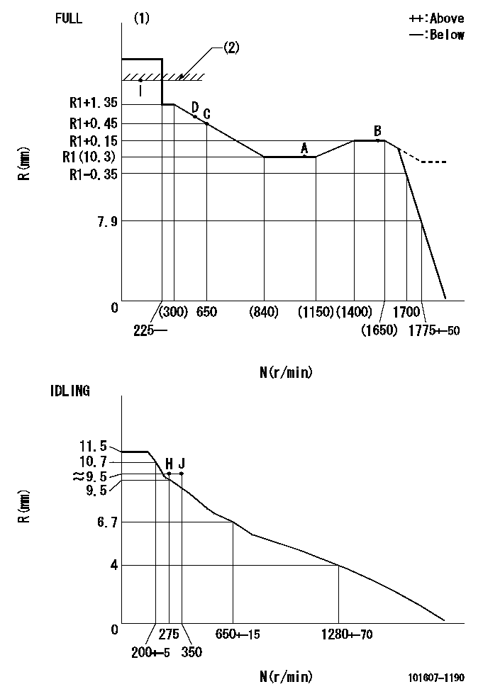
N:Pump speed
R:Rack position (mm)
(1)Torque cam stamping: T1
(2)RACK LIMIT
----------
T1=C26
----------
----------
T1=C26
----------
Speed control lever angle

F:Full speed
I:Idle
(1)Use the hole at R = aa
(2)Stopper bolt set position 'H'
----------
aa=40mm
----------
a=26deg+-5deg b=37deg+-3deg
----------
aa=40mm
----------
a=26deg+-5deg b=37deg+-3deg
Stop lever angle

N:Engine manufacturer's normal use
S:Stop the pump.
(1)Free (at shipping)
(2)Use the hole at R = aa
(3)Rack position corresponding to bb
(4)Set the stopper bolt so that speed = cc and rack position = dd.
(5)After setting the stopper bolt, confirm non-injection at speed ee. (Rack position = ff or less)
----------
aa=40mm bb=16mm cc=1700r/min dd=6.5-0.5mm ee=275r/min ff=8mm
----------
a=8deg+-5deg b=15deg+-5deg c=25deg+-5deg
----------
aa=40mm bb=16mm cc=1700r/min dd=6.5-0.5mm ee=275r/min ff=8mm
----------
a=8deg+-5deg b=15deg+-5deg c=25deg+-5deg
Timing setting

(1)Pump vertical direction
(2)Position of gear mark '3' at No 1 cylinder's beginning of injection
(3)B.T.D.C.: aa
(4)-
----------
aa=12deg
----------
a=(130deg)
----------
aa=12deg
----------
a=(130deg)
Information:
Functional Test
PC-33: Injector Solenoids Circuit Test
System Operation
Schematic ECM Pin Locations Diagnostic Codes
Functional Test
PC-34: +5V Sensor Voltage Supply Circuit Test
System Operation
Schematic ECM Pin Locations Diagnostic Codes
Functional Test
PC-35: Engine Sensor Open or Short Circuit Test
System Operation
Schematic ECM Pin Locations Diagnostic Codes
Functional Test
PC-36: Injection Actuation Pressure Sensor Test
System Operation
Schematic Diagnostic Codes
Functional Test
PC-37: Injection Actuation Pressure Control Valve Circuit Test
System Operation
Schematic ECM Pin Locations Diagnostic Codes
Functional Test
PC-38: Injection Actuation Pressure System Test
System Operation
Diagnostic Codes
Functional Test
PC-39: Inlet Air Heater Circuit Test
System Operation
Schematic ECM Pin Locations Diagnostic Codes
Inlet Air Heater Operation Chart (Personality Modules before JUN97) Inlet Air Heater Operation Chart (JUN97 and later Personality Modules) Functional Test
PC-40: Event Codes Test
System Operation
Diagnostic Codes
Functional Test
Have questions with 101607-1190?
Group cross 101607-1190 ZEXEL
Mitsubishi
Mitsubishi
Mitsubishi
Mitsubishi
Mitsubishi
101607-1190
9 400 615 598
ME086626
INJECTION-PUMP ASSEMBLY
6D31
6D31