Information injection-pump assembly
BOSCH
9 400 615 597
9400615597
ZEXEL
101607-1170
1016071170
MITSUBISHI
ME076656
me076656

Rating:
Service parts 101607-1170 INJECTION-PUMP ASSEMBLY:
1.
_
6.
COUPLING PLATE
7.
COUPLING PLATE
8.
_
9.
_
10.
NOZZLE AND HOLDER ASSY
11.
Nozzle and Holder
12.
Open Pre:MPa(Kqf/cm2)
15.7{160}/21.6{220}
14.
NOZZLE
15.
NOZZLE SET
Cross reference number
BOSCH
9 400 615 597
9400615597
ZEXEL
101607-1170
1016071170
MITSUBISHI
ME076656
me076656
Zexel num
Bosch num
Firm num
Name
101607-1170
9 400 615 597
ME076656 MITSUBISHI
INJECTION-PUMP ASSEMBLY
6D14 * K 14BE INJECTION PUMP ASSY PE6A PE
6D14 * K 14BE INJECTION PUMP ASSY PE6A PE
Calibration Data:
Adjustment conditions
Test oil
1404 Test oil ISO4113 or {SAEJ967d}
1404 Test oil ISO4113 or {SAEJ967d}
Test oil temperature
degC
40
40
45
Nozzle and nozzle holder
105780-8140
Bosch type code
EF8511/9A
Nozzle
105780-0000
Bosch type code
DN12SD12T
Nozzle holder
105780-2080
Bosch type code
EF8511/9
Opening pressure
MPa
17.2
Opening pressure
kgf/cm2
175
Injection pipe
Outer diameter - inner diameter - length (mm) mm 6-2-600
Outer diameter - inner diameter - length (mm) mm 6-2-600
Overflow valve
131424-5520
Overflow valve opening pressure
kPa
255
221
289
Overflow valve opening pressure
kgf/cm2
2.6
2.25
2.95
Tester oil delivery pressure
kPa
157
157
157
Tester oil delivery pressure
kgf/cm2
1.6
1.6
1.6
Direction of rotation (viewed from drive side)
Left L
Left L
Injection timing adjustment
Direction of rotation (viewed from drive side)
Left L
Left L
Injection order
1-5-3-6-
2-4
Pre-stroke
mm
3.3
3.25
3.35
Beginning of injection position
Governor side NO.1
Governor side NO.1
Difference between angles 1
Cal 1-5 deg. 60 59.5 60.5
Cal 1-5 deg. 60 59.5 60.5
Difference between angles 2
Cal 1-3 deg. 120 119.5 120.5
Cal 1-3 deg. 120 119.5 120.5
Difference between angles 3
Cal 1-6 deg. 180 179.5 180.5
Cal 1-6 deg. 180 179.5 180.5
Difference between angles 4
Cyl.1-2 deg. 240 239.5 240.5
Cyl.1-2 deg. 240 239.5 240.5
Difference between angles 5
Cal 1-4 deg. 300 299.5 300.5
Cal 1-4 deg. 300 299.5 300.5
Injection quantity adjustment
Adjusting point
-
Rack position
11.4
Pump speed
r/min
850
850
850
Each cylinder's injection qty
mm3/st.
62.9
61
64.8
Basic
*
Fixing the rack
*
Standard for adjustment of the maximum variation between cylinders
*
Injection quantity adjustment_02
Adjusting point
C
Rack position
9.2+-0.5
Pump speed
r/min
275
275
275
Each cylinder's injection qty
mm3/st.
10
8.5
11.5
Fixing the rack
*
Standard for adjustment of the maximum variation between cylinders
*
Injection quantity adjustment_03
Adjusting point
A
Rack position
R1(11.4)
Pump speed
r/min
850
850
850
Average injection quantity
mm3/st.
62.9
61.9
63.9
Basic
*
Fixing the lever
*
Injection quantity adjustment_04
Adjusting point
B
Rack position
R1(11.4)
Pump speed
r/min
1450
1450
1450
Average injection quantity
mm3/st.
72.1
68.1
76.1
Fixing the lever
*
Injection quantity adjustment_05
Adjusting point
E
Rack position
12.2+-0.
1
Pump speed
r/min
500
500
500
Average injection quantity
mm3/st.
64.6
62.6
66.6
Fixing the lever
*
Remarks
Startup boost setting
Startup boost setting
Timer adjustment
Pump speed
r/min
1250--
Advance angle
deg.
0
0
0
Remarks
Start
Start
Timer adjustment_02
Pump speed
r/min
1200
Advance angle
deg.
0.5
Timer adjustment_03
Pump speed
r/min
1400
Advance angle
deg.
5
4.5
5.5
Remarks
Finish
Finish
Test data Ex:
Governor adjustment
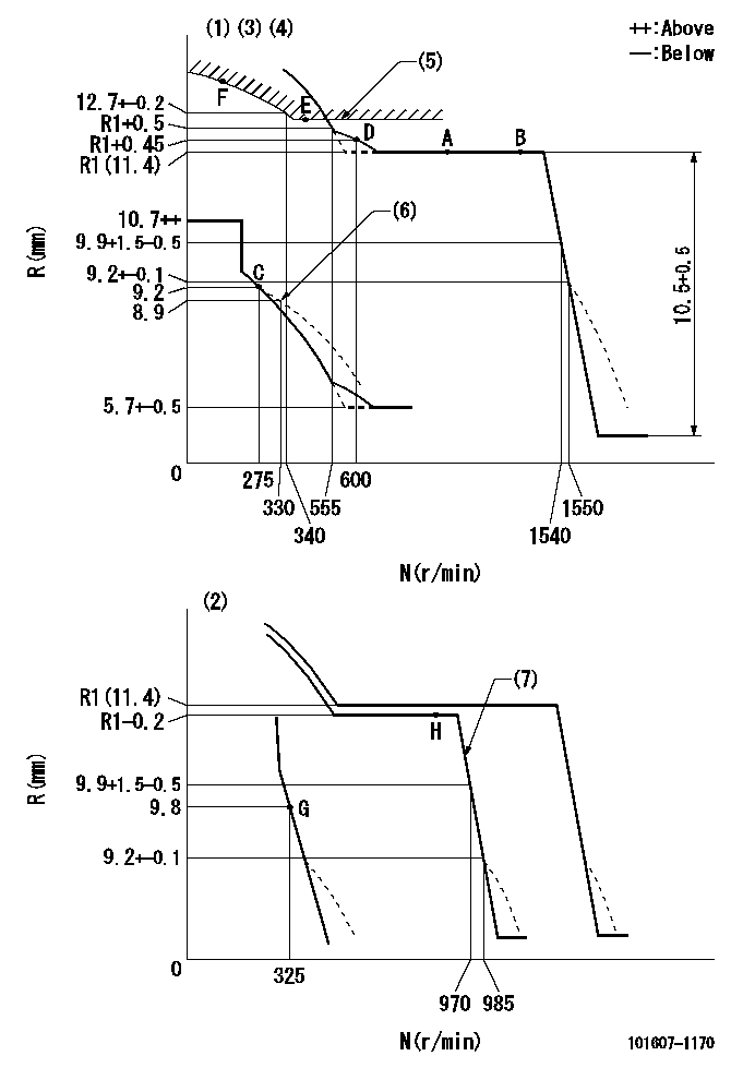
N:Pump speed
R:Rack position (mm)
(1)Adjust with speed control lever at full position (minimum-maximum speed specification)
(2)Adjust with the load control lever in the full position (variable speed specification).
(3)Lever ratio: RT
(4)Target shim dimension: TH
(5)Excess fuel setting for starting: SXL
(6)Damper spring setting
(7)When air cylinder is operating.
----------
RT=1 TH=2.8mm SXL=12.2+-0.1mm
----------
----------
RT=1 TH=2.8mm SXL=12.2+-0.1mm
----------
Speed control lever angle
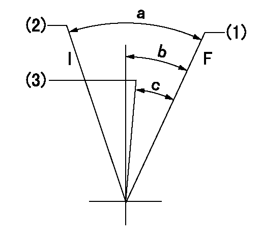
F:Full speed
I:Idle
(1)Pump speed = aa
(2)Pump speed = bb
(3)Pump speed cc
----------
aa=1540r/min bb=325r/min cc=970r/min
----------
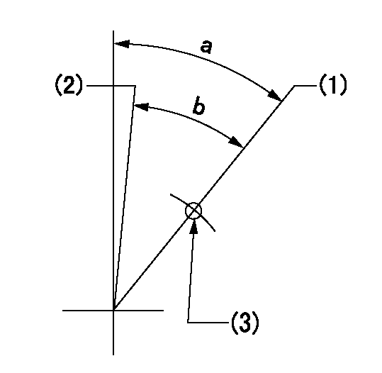
a=24deg+-5deg b=16deg+-5deg c=(14deg)+-5deg
----------
aa=1540r/min bb=325r/min cc=970r/min
----------
a=24deg+-5deg b=16deg+-5deg c=(14deg)+-5deg
0000000901
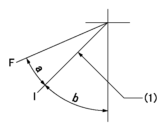
F:Full load
I:Idle
(1)Stopper bolt setting
----------
----------
a=21deg+-3deg b=30deg+-5deg
----------
----------
a=21deg+-3deg b=30deg+-5deg
Stop lever angle
S:Stop the pump.
(1)Free (at shipping)
(2)Rack position = aa (confirm non-injection at speed = bb).
----------
aa=7-0.5mm bb=1600r/min
----------
a=1deg+-5deg b=49deg+7deg-5deg
----------
aa=7-0.5mm bb=1600r/min
----------
a=1deg+-5deg b=49deg+7deg-5deg
0000001201
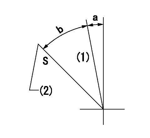
(1)Minimum - maximum speed specification
(2)Variable speed specification
(3)Use the hole at R = aa
----------
aa=70mm
----------
a=33deg+-3deg b=30deg+-5deg
----------
aa=70mm
----------
a=33deg+-3deg b=30deg+-5deg
0000001501 2-STAGE CHANGEOVER DEVICE

RFD governor 2 stage changeover mechanism adjustment outline
(A) Bolt
(B) bolt
(c) Nut
(D) Return spring
(E) Bolt
(F) Bolt
(G) Screw
(H) Bolt
(I) Load lever
(J) Speed lever
(K) Air cylinder
(M Air inlet
Figure 1 is only for reference. Lever shape, etc, may vary.
1. Minimum-maximum speed specification adjustment (when running)
(a) Without applying air to the air cylinder, loosen bolts (A) and (B).
(1)High speed return L setting
(a) In the speed range Nf~Nf - 300r/min, adjust using the speed adjusting bolt to determine the temporary beginning of high speed control speed.
(b) Determine the rack position in the vicinity of Rf using the full load lever.
(c) Increase speed and confirm return distance L.
(d) Adjust using the tension lever bolt to obtain L.
(2)Setting full load rack position Rf
(a) Move the load control lever to the full side.
(b) Adjust the full load adjusting bolt so that Rf can be obtained, then fix.
(3)Setting the beginning of high speed operation Nf
(a) Adjust using bolt (E) so that Nf can be obtained, and then fix.
(4)Idle control setting (Re, Ni, Rc)
(a) Set the speed at Ns + 200r/min and move the load control lever to the idle side.
(b) Fix the lever in the position where Re can be obtained.
(c) Next, decrease speed to Ni and screw in the idle spring.
(d) Adjust to obtain rack position Ri.
(e) Increase the speed and after confirming that the rack position is Re at Ns, set the speed at 0.
(f) Confirm protrusion position Rc at idle.
(5)Damper spring adjustment
(a) Increase speed and set the speed at the rack position Rd - 0.1 mm
(b) Set using the damper spring so that the rack position Rd can be obtained.
(c) When Rd is not specified, Rd = Ri - 0.5 mm.
(6)High speed droop confirmation
(a) Return the load control lever to the full load lever position.
(b) Increase the speed and confirm that Rf can be obtained at Nf r/min.
(c) Confirm that speed is Nh at rack position Rh.
2. Variable speed specification adjustment (at operation)
(a) Remove return spring (D).
(b) Apply air pressure of 245~294 kPa {2.5~3 kg/cm2} to the air cylinder.
(c) Perform the following adjustment in this condition.
(1)Setting full load rack position Rf'
(a) Pull the load lever to the idle side.
(b) Obtain rack position Rf' using the nut (C). (Pump speed is Nf'-50 r/min.)
(2)Setting full speed Nf'
(a) Adjust using bolt (B) so that Nf can be obtained, and then fix.
(3)Low speed side setting
(a) At 350r/min, set bolt (F) at beginning of governor operation position, then fix.
3. Bolt (A) adjustment
(1)Install return spring (D) and perform the adjustments below at air pressure 0.
(a) Set at speed Nf using bolt (E).
(b) Screw in bolt (A).
(c) Screw in 1 more turn from the speed lever contact position
(d) Fix bolt (A).
(e) At this time confirm that the air cylinder's shaft moves approximately 1 mm towards the governor.
4. Lever operation confirmation using the air cylinder
(1)Apply 588 kPa {6 kg/cm2} air pressure to the air cylinder.
(2)Confirm that the cylinder piston is moved 50 mm by the spring (D).
----------
----------
----------
----------
0000001601 MICRO SWITCH
Adjustment of the micro-switch
Adjust the bolt to obtain the following lever position when the micro-switch is ON.
(1)Speed N1
(2)Rack position Ra
----------
N1=400r/min Ra=8.9+-0.1mm
----------
----------
N1=400r/min Ra=8.9+-0.1mm
----------
Timing setting

(1)Pump vertical direction
(2)Position of timer's tooth at No 1 cylinder's beginning of injection
(3)B.T.D.C.: aa
(4)-
----------
aa=13deg
----------
a=(0deg)
----------
aa=13deg
----------
a=(0deg)
Information:
Programming a Personality Module Using Flash Programming
Operation of the engine following programming of the Personality Module is identical to operation following replacement of the Personality Module chip. The only difference is the software was already programmed into the chip for you when you replaced the chip. Now you are actually performing the programming function. For example, if rerating an engine, there is still a need for Factory Passwords to change the Personality Module Code.1. Connect components as shown below. 2. Start the LEXT3037 PC Program.3. Select the engine Personality Module part number to be programmed into the ECM, and proceed with programming the Personality Module. A new ECM is shipped with a blank Personality Module.4. PC Program Personality Module Messages and Their Meaning. A new ECM comes with a blank (previously unprogrammed) personality module. A blank personality module will prompt you for all three of the following messages. The information contained in the "ECM Status" will be scrambled and meaningless if the module has not been previously programmed (this is normal).- Message - "The engine ID in the flash file does not match the engine ID in the ECM."- Meaning - The ECM has a personality module for a different engine. For example, the ECM has a 3116 personality module, and you are attempting to program a 3126 personality module.- What you should do. Stop the transfer and access information about "ECM Status" under the "Electronic Control Module" menu. Ensure the file you are about to transfer is for the same engine it will be installed.- Message- "The application ID in the flash file does not match the application ID in the ECM."- Meaning- The ECM has a personality module for a different application. For example, the ECM has a 3126 On-Highway Truck personality module and you are attempting to program a 3126 Marine personality module.- What you should do. Stop the transfer and access information about "ECM Status" under the "Electronic Control Module" menu. Ensure the file you are about to transfer is for the On-Highway Truck application.- Message- "The ECM ID in the flash file does not match the ECM ID in the ECM."- Meaning- The ECM is not for use in the 3100 HEUI On-Highway truck application.- What you should do. Stop the transfer and access information about "ECM Status" under the "Electronic Control Module" menu. Ensure the ECM on the engine is for a 3100 HEUI On-Highway truck application. If you access the "ECM Status" under the "Electronic Control Module" menu of the PC Program, but do not follow this information access by programming the Personality Module, turn the vehicle ignition key switch to the OFF position, and then to the ON position before using an ECAP or ET. If the ignition key switch is not cycled after reading the "ECM Status", the ECM will not communicate with your Service Tool, or start. Cycling the ignition key switch is not necessary following successful programming of a Personality Module using the Flash Designer Program.5. Start
Operation of the engine following programming of the Personality Module is identical to operation following replacement of the Personality Module chip. The only difference is the software was already programmed into the chip for you when you replaced the chip. Now you are actually performing the programming function. For example, if rerating an engine, there is still a need for Factory Passwords to change the Personality Module Code.1. Connect components as shown below. 2. Start the LEXT3037 PC Program.3. Select the engine Personality Module part number to be programmed into the ECM, and proceed with programming the Personality Module. A new ECM is shipped with a blank Personality Module.4. PC Program Personality Module Messages and Their Meaning. A new ECM comes with a blank (previously unprogrammed) personality module. A blank personality module will prompt you for all three of the following messages. The information contained in the "ECM Status" will be scrambled and meaningless if the module has not been previously programmed (this is normal).- Message - "The engine ID in the flash file does not match the engine ID in the ECM."- Meaning - The ECM has a personality module for a different engine. For example, the ECM has a 3116 personality module, and you are attempting to program a 3126 personality module.- What you should do. Stop the transfer and access information about "ECM Status" under the "Electronic Control Module" menu. Ensure the file you are about to transfer is for the same engine it will be installed.- Message- "The application ID in the flash file does not match the application ID in the ECM."- Meaning- The ECM has a personality module for a different application. For example, the ECM has a 3126 On-Highway Truck personality module and you are attempting to program a 3126 Marine personality module.- What you should do. Stop the transfer and access information about "ECM Status" under the "Electronic Control Module" menu. Ensure the file you are about to transfer is for the On-Highway Truck application.- Message- "The ECM ID in the flash file does not match the ECM ID in the ECM."- Meaning- The ECM is not for use in the 3100 HEUI On-Highway truck application.- What you should do. Stop the transfer and access information about "ECM Status" under the "Electronic Control Module" menu. Ensure the ECM on the engine is for a 3100 HEUI On-Highway truck application. If you access the "ECM Status" under the "Electronic Control Module" menu of the PC Program, but do not follow this information access by programming the Personality Module, turn the vehicle ignition key switch to the OFF position, and then to the ON position before using an ECAP or ET. If the ignition key switch is not cycled after reading the "ECM Status", the ECM will not communicate with your Service Tool, or start. Cycling the ignition key switch is not necessary following successful programming of a Personality Module using the Flash Designer Program.5. Start
Have questions with 101607-1170?
Group cross 101607-1170 ZEXEL
Mitsubishi
Mitsubishi
Mitsubishi
Mitsubishi
Mitsubishi
101607-1170
9 400 615 597
ME076656
INJECTION-PUMP ASSEMBLY
6D14
6D14