Information injection-pump assembly
BOSCH
9 400 615 590
9400615590
ZEXEL
101607-1102
1016071102
MITSUBISHI
ME076611
me076611
Rating:
Include in #1:
101402-7290
as _
Cross reference number
BOSCH
9 400 615 590
9400615590
ZEXEL
101607-1102
1016071102
MITSUBISHI
ME076611
me076611
Zexel num
Bosch num
Firm num
Name
101607-1102
9 400 615 590
ME076611 MITSUBISHI
INJECTION-PUMP ASSEMBLY
6D16 * K
6D16 * K
Calibration Data:
Adjustment conditions
Test oil
1404 Test oil ISO4113 or {SAEJ967d}
1404 Test oil ISO4113 or {SAEJ967d}
Test oil temperature
degC
40
40
45
Nozzle and nozzle holder
105780-8140
Bosch type code
EF8511/9A
Nozzle
105780-0000
Bosch type code
DN12SD12T
Nozzle holder
105780-2080
Bosch type code
EF8511/9
Opening pressure
MPa
17.2
Opening pressure
kgf/cm2
175
Injection pipe
Outer diameter - inner diameter - length (mm) mm 6-2-600
Outer diameter - inner diameter - length (mm) mm 6-2-600
Overflow valve
131424-5520
Overflow valve opening pressure
kPa
255
221
289
Overflow valve opening pressure
kgf/cm2
2.6
2.25
2.95
Tester oil delivery pressure
kPa
157
157
157
Tester oil delivery pressure
kgf/cm2
1.6
1.6
1.6
Direction of rotation (viewed from drive side)
Left L
Left L
Injection timing adjustment
Direction of rotation (viewed from drive side)
Left L
Left L
Injection order
1-5-3-6-
2-4
Pre-stroke
mm
3.2
3.15
3.25
Beginning of injection position
Governor side NO.1
Governor side NO.1
Difference between angles 1
Cal 1-5 deg. 60 59.5 60.5
Cal 1-5 deg. 60 59.5 60.5
Difference between angles 2
Cal 1-3 deg. 120 119.5 120.5
Cal 1-3 deg. 120 119.5 120.5
Difference between angles 3
Cal 1-6 deg. 180 179.5 180.5
Cal 1-6 deg. 180 179.5 180.5
Difference between angles 4
Cyl.1-2 deg. 240 239.5 240.5
Cyl.1-2 deg. 240 239.5 240.5
Difference between angles 5
Cal 1-4 deg. 300 299.5 300.5
Cal 1-4 deg. 300 299.5 300.5
Injection quantity adjustment
Adjusting point
-
Rack position
11.6
Pump speed
r/min
850
850
850
Each cylinder's injection qty
mm3/st.
72.5
70.3
74.7
Basic
*
Fixing the rack
*
Standard for adjustment of the maximum variation between cylinders
*
Injection quantity adjustment_02
Adjusting point
H
Rack position
9.5+-0.5
Pump speed
r/min
275
275
275
Each cylinder's injection qty
mm3/st.
8.3
7.1
9.5
Fixing the rack
*
Standard for adjustment of the maximum variation between cylinders
*
Injection quantity adjustment_03
Adjusting point
A
Rack position
R1(11.6)
Pump speed
r/min
850
850
850
Average injection quantity
mm3/st.
72.5
71.5
73.5
Basic
*
Fixing the lever
*
Injection quantity adjustment_04
Adjusting point
B
Rack position
R1-0.15
Pump speed
r/min
1400
1400
1400
Average injection quantity
mm3/st.
79.5
75.5
83.5
Fixing the lever
*
Injection quantity adjustment_05
Adjusting point
C
Rack position
R1+0.65
Pump speed
r/min
500
500
500
Average injection quantity
mm3/st.
71.5
67.5
75.5
Fixing the lever
*
Injection quantity adjustment_06
Adjusting point
I
Rack position
14.8+-0.
2
Pump speed
r/min
100
100
100
Average injection quantity
mm3/st.
120
100
140
Fixing the lever
*
Rack limit
*
Timer adjustment
Pump speed
r/min
1150
Advance angle
deg.
0.5
Timer adjustment_02
Pump speed
r/min
1200
Advance angle
deg.
0.9
0.4
1.4
Timer adjustment_03
Pump speed
r/min
1380
Advance angle
deg.
5
4.5
5.5
Remarks
Finish
Finish
Test data Ex:
Governor adjustment
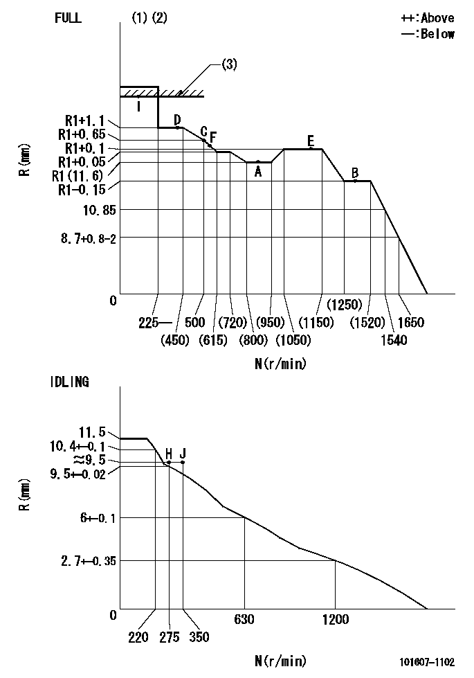
N:Pump speed
R:Rack position (mm)
(1)Torque cam stamping: T1
(2)Tolerance for racks not indicated: +-0.05mm.
(3)RACK LIMIT: RAL
----------
T1=G26 RAL=14.8+-0.2mm
----------
----------
T1=G26 RAL=14.8+-0.2mm
----------
Speed control lever angle

F:Full speed
I:Idle
(1)Stopper bolt set position 'H'
----------
----------
a=18.5deg+-5deg b=(40deg)+-3deg
----------
----------
a=18.5deg+-5deg b=(40deg)+-3deg
Stop lever angle

N:Engine manufacturer's normal use
S:Stop the pump.
(1)Set the stopper bolt at pump speed = aa and rack position = bb (non-injection rack position). Confirm non-injection.
(2)After setting the stopper bolt, confirm non-injection at speed cc. Rack position = dd (non-injection rack position).
(3)Rack position = approximately ee.
(4)Free (at shipping)
----------
aa=1400r/min bb=6.9-0.5mm cc=275r/min dd=(8.9)-0.5mm ee=15mm
----------
a=36.5deg+-5deg b=(25deg) c=13.5deg+-5deg
----------
aa=1400r/min bb=6.9-0.5mm cc=275r/min dd=(8.9)-0.5mm ee=15mm
----------
a=36.5deg+-5deg b=(25deg) c=13.5deg+-5deg
0000001501 MICRO SWITCH
Adjustment of the micro-switch
Adjust the bolt to obtain the following lever position when the micro-switch is ON.
(1)Speed N1
(2)Rack position Ra
----------
N1=400r/min Ra=9.2+-0.1mm
----------
----------
N1=400r/min Ra=9.2+-0.1mm
----------
Timing setting

(1)Pump vertical direction
(2)Position of timer's tooth at No 1 cylinder's beginning of injection
(3)B.T.D.C.: aa
(4)-
----------
aa=11deg
----------
a=(1deg)
----------
aa=11deg
----------
a=(1deg)
Information:
The 169-3374 Injector Sleeve Removal Group is used to remove the brass injector sleeves on 3176 and 3176B Engines, only. This tool group is used with the 9U-6860 Sleeve Replacement Group . The tool group eliminates the tapping and threading operation of the current 9U-6860 Sleeve Replacement Group . The benefits of this method of sleeve removal are easier sleeve removal and little debris that could enter the engine. This tool group uses a crimping die and captured stud similar to the current 3100 Sleeve Removal Tool. This tool group can be used with the cylinder head either on or off the engine.Additional Contact Information
For additional product support questions concerning this tool, contact the Dealer Service Tools Hotline at:USA: 1-800-542-8665, Option 1International: 1-309-578-7372Injector Sleeve Removal
Remove the rocker arms from the cylinder being repaired.
Remove the injector.
Illustration 4 g02888499
Put Sleeve Stud (3) into Injector Sleeve
Drop 142-8280 Sleeve Stud (3) into the injector sleeve and ensure that stud is resting at the bottom of the injector sleeve. The flat disc part of the sleeve stud should be below the top edge of the brass sleeve.
Illustration 5 g02888500
Insert Crimping Swage (9) Into Bore And Over Sleeve Stud (3)
Apply a light coating of grease to the inside cutting edge of crimping swage (9) and insert into the injector bore. Make sure that the tool is resting on the top edge of the brass sleeve by turning or "wiggling" slightly. It is possible for the tool to rest on the casting ledge (indicated by the arrow) in the cylinder head. The threads of sleeve stud (3) should go into the center hole of crimping swage (9), as shown in Figure 5.
Illustration 6 g02888508
Drive Crimping Swage (9) Down Into Injector Sleeve
Using a large hammer, strike the top of crimping swage (9) firmly and squarely. Drive down into the injector bore until the bottom slot is level with the top deck of the cylinder head, as shown in Figure 6.
Illustration 7 g02888509
Remove Driving Swage (9) With Crows Foot Pry Bar (12)
Remove the crimping swage from the injector bore. If the tool is stuck in the bore, use a crows foot pry bar (12) in the slot to work out the tool. Many times there will be a small amount of brass caught between crimping swage (9) and the injector bore causing the tool to stick. When the tool is removed, the top of the brass sleeve should be rolled over, trapping sleeve stud (3) inside the injector sleeve.Note: The sharp edge of crimping swage (9) must remain sharp and free of nicks or damage. This tool may be resharpened only on the inside cutting edge. Any sharpening procedure that reduces the OD of the cutting edge will result in poor tool performance and tool sticking.
Illustration 8 g02888517
Insert Sleeve Jaw (4)
Insert 151-4833 Sleeve Jaw (4) into the injector bore. The sharp edge of the sleeve jaw is designed to lock the rolled-over brass material between the sleeve stud and the sleeve jaw. The sleeve stud is then prevented from
Have questions with 101607-1102?
Group cross 101607-1102 ZEXEL
Mitsubishi
101607-1102
9 400 615 590
ME076611
INJECTION-PUMP ASSEMBLY
6D16
6D16