Information injection-pump assembly
ZEXEL
101607-1092
1016071092
MITSUBISHI
ME076608
me076608
Rating:
Cross reference number
ZEXEL
101607-1092
1016071092
MITSUBISHI
ME076608
me076608
Zexel num
Bosch num
Firm num
Name
101607-1092
ME076608 MITSUBISHI
INJECTION-PUMP ASSEMBLY
6D16 * K
6D16 * K
Calibration Data:
Adjustment conditions
Test oil
1404 Test oil ISO4113 or {SAEJ967d}
1404 Test oil ISO4113 or {SAEJ967d}
Test oil temperature
degC
40
40
45
Nozzle and nozzle holder
105780-8140
Bosch type code
EF8511/9A
Nozzle
105780-0000
Bosch type code
DN12SD12T
Nozzle holder
105780-2080
Bosch type code
EF8511/9
Opening pressure
MPa
17.2
Opening pressure
kgf/cm2
175
Injection pipe
Outer diameter - inner diameter - length (mm) mm 6-2-600
Outer diameter - inner diameter - length (mm) mm 6-2-600
Overflow valve
131424-5520
Overflow valve opening pressure
kPa
255
221
289
Overflow valve opening pressure
kgf/cm2
2.6
2.25
2.95
Tester oil delivery pressure
kPa
157
157
157
Tester oil delivery pressure
kgf/cm2
1.6
1.6
1.6
Direction of rotation (viewed from drive side)
Left L
Left L
Injection timing adjustment
Direction of rotation (viewed from drive side)
Left L
Left L
Injection order
1-5-3-6-
2-4
Pre-stroke
mm
3.2
3.15
3.25
Beginning of injection position
Governor side NO.1
Governor side NO.1
Difference between angles 1
Cal 1-5 deg. 60 59.5 60.5
Cal 1-5 deg. 60 59.5 60.5
Difference between angles 2
Cal 1-3 deg. 120 119.5 120.5
Cal 1-3 deg. 120 119.5 120.5
Difference between angles 3
Cal 1-6 deg. 180 179.5 180.5
Cal 1-6 deg. 180 179.5 180.5
Difference between angles 4
Cyl.1-2 deg. 240 239.5 240.5
Cyl.1-2 deg. 240 239.5 240.5
Difference between angles 5
Cal 1-4 deg. 300 299.5 300.5
Cal 1-4 deg. 300 299.5 300.5
Injection quantity adjustment
Adjusting point
-
Rack position
11.6
Pump speed
r/min
850
850
850
Each cylinder's injection qty
mm3/st.
72.5
70.3
74.7
Basic
*
Fixing the rack
*
Standard for adjustment of the maximum variation between cylinders
*
Injection quantity adjustment_02
Adjusting point
H
Rack position
9.5+-0.5
Pump speed
r/min
275
275
275
Each cylinder's injection qty
mm3/st.
8.3
7.1
9.5
Fixing the rack
*
Standard for adjustment of the maximum variation between cylinders
*
Injection quantity adjustment_03
Adjusting point
A
Rack position
R1(11.6)
Pump speed
r/min
850
850
850
Average injection quantity
mm3/st.
72.5
71.5
73.5
Basic
*
Fixing the lever
*
Injection quantity adjustment_04
Adjusting point
B
Rack position
R1-0.15
Pump speed
r/min
1400
1400
1400
Average injection quantity
mm3/st.
79.5
75.5
83.5
Fixing the lever
*
Injection quantity adjustment_05
Adjusting point
C
Rack position
R1+0.65
Pump speed
r/min
500
500
500
Average injection quantity
mm3/st.
71.5
67.5
75.5
Fixing the lever
*
Injection quantity adjustment_06
Adjusting point
I
Rack position
14.8+-0.
2
Pump speed
r/min
100
100
100
Average injection quantity
mm3/st.
120
100
140
Fixing the lever
*
Rack limit
*
Timer adjustment
Pump speed
r/min
1150
Advance angle
deg.
0.5
Timer adjustment_02
Pump speed
r/min
1200
Advance angle
deg.
0.9
0.4
1.4
Timer adjustment_03
Pump speed
r/min
1380
Advance angle
deg.
5
4.5
5.5
Remarks
Finish
Finish
Test data Ex:
Governor adjustment
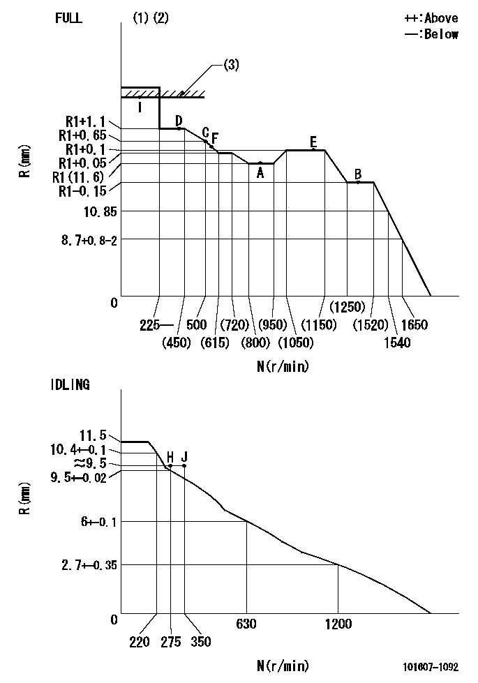
N:Pump speed
R:Rack position (mm)
(1)Torque cam stamping: T1
(2)Tolerance for racks not indicated: +-0.05mm.
(3)RACK LIMIT: RAL
----------
T1=G26 RAL=14.8+-0.2mm
----------
----------
T1=G26 RAL=14.8+-0.2mm
----------
Speed control lever angle

F:Full speed
I:Idle
(1)Stopper bolt set position 'H'
----------
----------
a=18.5deg+-5deg b=(40deg)+-3deg
----------
----------
a=18.5deg+-5deg b=(40deg)+-3deg
Stop lever angle
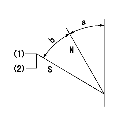
N:Pump normal
S:Stop the pump.
(1)Set the stopper bolt at pump speed = aa and rack position = bb (non-injection rack position). Confirm non-injection.
(2)After setting the stopper bolt, confirm non-injection at speed cc. Rack position = dd (non-injection rack position).
----------
aa=1400r/min bb=6.9-0.5mm cc=275r/min dd=(8.9)-0.5mm
----------
a=11.5deg+-5deg b=25deg+-5deg
----------
aa=1400r/min bb=6.9-0.5mm cc=275r/min dd=(8.9)-0.5mm
----------
a=11.5deg+-5deg b=25deg+-5deg
0000001501 MICRO SWITCH
Adjustment of the micro-switch
Adjust the bolt to obtain the following lever position when the micro-switch is ON.
(1)Speed N1
(2)Rack position Ra
----------
N1=400r/min Ra=9.2+-0.1mm
----------
----------
N1=400r/min Ra=9.2+-0.1mm
----------
0000001601 LEVER
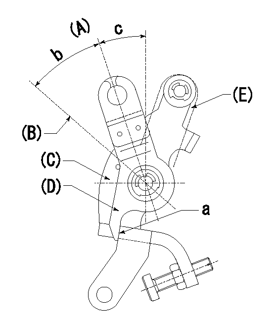
(A) Idle
(B) Full speed
(C) Base lever
(D) Accelerator lever
(E) Accelerator lever delivery position
1. Measure speed lever angle
(1)Measure the angle when the accelerator lever (D) contacted the base lever (C) at a.
----------
----------
b=(40deg)+-3deg c=18.5deg+-5deg
----------
----------
b=(40deg)+-3deg c=18.5deg+-5deg
0000001701 RACK SENSOR

V1:Supply voltage
V2f:Full side output voltage
V2i:Idle side output voltage
(A) Black
(B) Yellow
(C) Red
(D) Trimmer
(E): Shaft
(F) Nut
(G) Load lever
1. Load sensor adjustment
(1)Connect as shown in the above diagram and apply supply voltage V1.
(2)Hold the load lever (G) against the full side.
(3)Turn the shaft so that the voltage between (A) and (B) is V2.
(4)Hold the load lever (G) against the idle side.
(5)Adjust (D) so that the voltage between (A) and (B) is V2i.
(6)Repeat the above adjustments.
(7)Tighten the nut (F) at the point satisfying the standards.
(8)Hold the load lever against the full side stopper and the idle side stopper.
(9)At this time, confirm that the full side output voltage is V2f and the idle side output voltage is V2i.
----------
V1=3.57+-0.02V V2f=3+0.05V V2i=1+0.1V
----------
----------
V1=3.57+-0.02V V2f=3+0.05V V2i=1+0.1V
----------
Timing setting

(1)Pump vertical direction
(2)Position of timer's tooth at No 1 cylinder's beginning of injection
(3)B.T.D.C.: aa
(4)-
----------
aa=11deg
----------
a=(1deg)
----------
aa=11deg
----------
a=(1deg)
Information:
Outside Leaks
Possible Causes/Corrections Leaks In Hoses Or ConnectionsCheck all hoses and connections for visual signs of leakage. If no leaks are seen, look for damage to hoses or loose clamps. Leaks In The Radiator And/Or Expansion TankPut pressure to the radiator and/or expansion tank with the 9S8140 Cooling System Pressurizing Pump Group and check for leaks. Leaks In The HeaterPut pressure to the cooling system with the 9S8140 Cooling System Pressurizing Pump Group and check the heater for leaks. Leaks In The Water PumpCheck the water pump for leaks before starting the engine, then start the engine and look for leaks. If there are leaks at the water pump, repair or install a new water pump. Cylinder Head Gasket LeakageLook for leaks along the surface of the cylinder head gasket. If you see leaks, install a new head gasket.Refer to Special Instruction, SEHS9565, 3306 Cylinder Head To Block Joint Repair Procedure for additional information on Combustion Gas Leakage Tests.Coolant Leaks At The Overflow Tube
Possible Causes/Corrections Defective Pressure Cap Or Relief ValveCheck the sealing surfaces of the pressure cap and the radiator to be sure the cap is sealing correctly. Check the opening pressure and sealing ability of the pressure cap or relief valve with the 9S8140 Cooling System Pressurizing Pump Group. Engine Runs Too HotIf coolant temperature is too high, pressure will be high enough to move the cap off of the sealing surface in the radiator and cause coolant loss through the overflow tube. See "Overheating" in Cooling System Troubleshooting Section. Expansion Tank Too Small Or Installed WrongThe expansion tank can be either a part of the radiator or it can be installed separately from the radiator. The expansion tank must be large enough to hold the expansion of the coolant as it gets warm or has sudden changes in pressure. Make sure the expansion tank is installed correctly, and the size is according to the recommendations of the truck manufacturer. Cylinder Head Gasket Leakage Or Crack(s) In Cylinder Head Or Cylinder BlockRemove the radiator cap and, with the engine running, look for air bubbles in the coolant. Bubbles in the coolant are a sign of probable leakage at the head gasket. Remove the cylinder head from the engine. Check cylinder head, cylinder walls and head gasket surface of the cylinder block for cracks. When the head is installed, use a new head gasket, spacer plate gasket, water seals, and O-ring seals.Inside Leakage
Possible Causes/Corrections Cylinder Head Gasket LeakageIf the cylinder head gasket leaks between a water passage and an opening into the crankcase, coolant will get into the crankcase.Refer to Special Instruction, SEHS9565, 3306 Cylinder Head To Block Joint Repair Procedure for additional information on Combustion Gas Leakage Tests. Crack(s) In Cylinder HeadCrack(s) in the upper surface of the cylinder head, or an area between a water passage and an opening into the crankcase, can allow coolant to get into the crankcase. Crack(s) In Cylinder BlockCrack(s) in the cylinder block between a water passage and the crankcase
Have questions with 101607-1092?
Group cross 101607-1092 ZEXEL
Mitsubishi
Mitsubishi
Mitsubishi
Mitsubishi
Mitsubishi
Mitsubishi
101607-1092
ME076608
INJECTION-PUMP ASSEMBLY
6D16
6D16