Information injection-pump assembly
BOSCH
F 01G 09U 04Y
f01g09u04y
ZEXEL
101607-1081
1016071081
Rating:
Cross reference number
BOSCH
F 01G 09U 04Y
f01g09u04y
ZEXEL
101607-1081
1016071081
Zexel num
Bosch num
Firm num
Name
Calibration Data:
Adjustment conditions
Test oil
1404 Test oil ISO4113 or {SAEJ967d}
1404 Test oil ISO4113 or {SAEJ967d}
Test oil temperature
degC
40
40
45
Nozzle and nozzle holder
105780-8140
Bosch type code
EF8511/9A
Nozzle
105780-0000
Bosch type code
DN12SD12T
Nozzle holder
105780-2080
Bosch type code
EF8511/9
Opening pressure
MPa
17.2
Opening pressure
kgf/cm2
175
Injection pipe
Outer diameter - inner diameter - length (mm) mm 6-2-600
Outer diameter - inner diameter - length (mm) mm 6-2-600
Overflow valve
131424-5520
Overflow valve opening pressure
kPa
255
221
289
Overflow valve opening pressure
kgf/cm2
2.6
2.25
2.95
Tester oil delivery pressure
kPa
157
157
157
Tester oil delivery pressure
kgf/cm2
1.6
1.6
1.6
Direction of rotation (viewed from drive side)
Left L
Left L
Injection timing adjustment
Direction of rotation (viewed from drive side)
Left L
Left L
Injection order
1-5-3-6-
2-4
Pre-stroke
mm
3.2
3.15
3.25
Beginning of injection position
Governor side NO.1
Governor side NO.1
Difference between angles 1
Cal 1-5 deg. 60 59.5 60.5
Cal 1-5 deg. 60 59.5 60.5
Difference between angles 2
Cal 1-3 deg. 120 119.5 120.5
Cal 1-3 deg. 120 119.5 120.5
Difference between angles 3
Cal 1-6 deg. 180 179.5 180.5
Cal 1-6 deg. 180 179.5 180.5
Difference between angles 4
Cyl.1-2 deg. 240 239.5 240.5
Cyl.1-2 deg. 240 239.5 240.5
Difference between angles 5
Cal 1-4 deg. 300 299.5 300.5
Cal 1-4 deg. 300 299.5 300.5
Injection quantity adjustment
Adjusting point
-
Rack position
11.6
Pump speed
r/min
850
850
850
Each cylinder's injection qty
mm3/st.
72.5
70.3
74.7
Basic
*
Fixing the rack
*
Standard for adjustment of the maximum variation between cylinders
*
Injection quantity adjustment_02
Adjusting point
H
Rack position
9.5+-0.5
Pump speed
r/min
275
275
275
Each cylinder's injection qty
mm3/st.
8.3
7.1
9.5
Fixing the rack
*
Standard for adjustment of the maximum variation between cylinders
*
Injection quantity adjustment_03
Adjusting point
A
Rack position
R1(11.6)
Pump speed
r/min
850
850
850
Average injection quantity
mm3/st.
72.5
71.5
73.5
Basic
*
Fixing the lever
*
Injection quantity adjustment_04
Adjusting point
B
Rack position
R1-0.15
Pump speed
r/min
1400
1400
1400
Average injection quantity
mm3/st.
79.5
75.5
83.5
Fixing the lever
*
Injection quantity adjustment_05
Adjusting point
C
Rack position
R1+0.65
Pump speed
r/min
500
500
500
Average injection quantity
mm3/st.
71.5
67.5
75.5
Fixing the lever
*
Injection quantity adjustment_06
Adjusting point
I
Rack position
14.8+-0.
2
Pump speed
r/min
100
100
100
Average injection quantity
mm3/st.
120
100
140
Fixing the lever
*
Rack limit
*
Timer adjustment
Pump speed
r/min
1150
Advance angle
deg.
0.5
Timer adjustment_02
Pump speed
r/min
1200
Advance angle
deg.
0.9
0.4
1.4
Timer adjustment_03
Pump speed
r/min
1380
Advance angle
deg.
5
4.5
5.5
Remarks
Finish
Finish
Test data Ex:
Governor adjustment
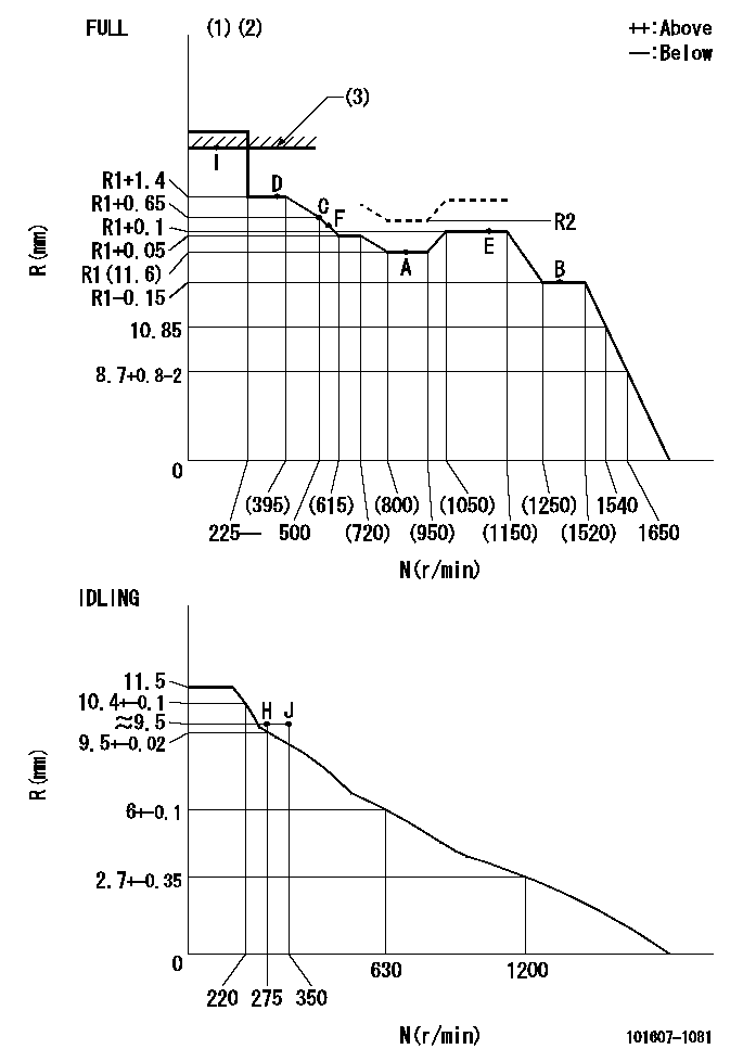
N:Pump speed
R:Rack position (mm)
(1)Torque cam stamping: T1
(2)Tolerance for racks not indicated: +-0.05mm.
(3)RACK LIMIT: RAL
----------
T1=F14 RAL=14.8+-0.2mm
----------
----------
T1=F14 RAL=14.8+-0.2mm
----------
Speed control lever angle

F:Full speed
I:Idle
(1)Stopper bolt set position 'H'
----------
----------
a=18.5deg+-5deg b=(40deg)+-3deg
----------
----------
a=18.5deg+-5deg b=(40deg)+-3deg
Stop lever angle
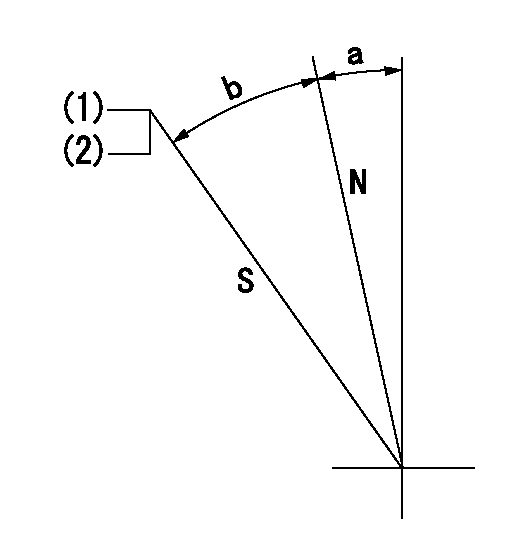
N:Pump normal
S:Stop the pump.
(1)Pump speed = aa and rack position = bb (non-injection rack position)
(2)Set the stopper bolt (confirm non-injection).
----------
aa=1400r/min bb=6.9-0.5mm
----------
a=11.5deg+-5deg b=25deg+-5deg
----------
aa=1400r/min bb=6.9-0.5mm
----------
a=11.5deg+-5deg b=25deg+-5deg
0000001501 MICRO SWITCH
Adjustment of the micro-switch
Adjust the bolt to obtain the following lever position when the micro-switch is ON.
(1)Speed N1
(2)Rack position Ra
----------
N1=400r/min Ra=9.2+-0.1mm
----------
----------
N1=400r/min Ra=9.2+-0.1mm
----------
0000001601 LEVER

(A) Accelerator lever stopper bolt
(B) Link
(c) Nut
(D) Lever
(E) Pin
(f) lever
(G) Stopper bolt
(H) Return spring
(J) Pin (E) contacts lever.
(K) Load sensor terminal
(1)Black
(2)Blue-yellow
(3)Blue-red
Setting the accelerator lever angle, load sensor adjustment
1. Accelerator lever setting method
(1)Position the speed lever against the idle stopper bolt and fix.
(2)Screw in the accelerator lever stopper bolt (A) and back off the stopper bolt (A) from the position where the accelerator lever pin contacts the speed lever and set. (Gap: approx. 1 mm)
Tightening torque: 4.9~7 N.m {0.5~0.7 kgf.m}
2. Load sensor adjustment (See fig 1)
(1)Load sensor output measuring circuit
Apply DC5+-0.01V to the load sensor terminals and measure the output voltage.
(2)Load sensor output adjustment procedure
Hold the speed lever against the full side stopper bolt and fix. Adjust the load sensor output voltage to VF = 0.417+-0.1 V using the link (B) and then fix temporarily using nut (C).
Turn the speed lever from the idle side to the full side and confirm that output voltage VF = 0.417+-0.1 V is obtained. Confirm several times and then fix using nut (C).
Tightening torque: 3.4~4.9 N.m {0.35~0.5 kgf.m}
3. Setting the step motor's idle side stopper bolt
After adjustment in previous 1 and 2, position speed lever against idle stopper bolt and fix. Then, screw in stopper bolt G until step motor lever D's pin E contacts lever F. Back off 10+2 deg (approx. 3.5 mm) from this position and fix G. (See fig. 3)
4. Speed lever return confirmation
(1)Remove return spring (H) and confirm that the speed lever is returned to the idle position by the torsion spring.
(2)Reinstall the return spring (H) in its original position.
----------
----------
----------
----------
0000001701 TAMPER PROOF
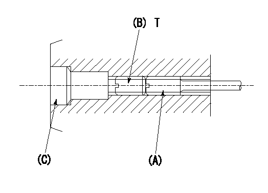
1. Method for setting tamperproof proofing
(1)After governor adjustment (torque cam phase adjustment), move the load lever to increase the full rack position to Ra.
(2)At speed N1 screw in screw (A) to obtain the rack position (actual measurement: Rb) for injection quantity Q1.
(3)Temporarily caulk using the tip of a screwdriver
(4)Confirm that the rack at that time is at Rc.
(5)Lock using setscrew (B). (Tightening torque = T)
(6)Next, coat (C) with adhesive and then pressfit.
(7)Then, readjust the full rack position using the load lever.
----------
N1=850r/min Q1=78.3+-1mm3/st Ra=(0.4)mm Rb=R2mm Rc=R2mm
----------
T=3.4~4.9N-m(0.35~0.5Kgf-m)
----------
N1=850r/min Q1=78.3+-1mm3/st Ra=(0.4)mm Rb=R2mm Rc=R2mm
----------
T=3.4~4.9N-m(0.35~0.5Kgf-m)
Timing setting

(1)Pump vertical direction
(2)Position of timer's tooth at No 1 cylinder's beginning of injection
(3)B.T.D.C.: aa
(4)-
----------
aa=11deg
----------
a=(1deg)
----------
aa=11deg
----------
a=(1deg)
Information:
Exhaust Smoke Can Be Seen While Starting
Possible Causes/Corrections Cold Outside TemperaturesIt may be necessary to use starting aids, or to heat engine oil or coolant at temperatures below -12°C (10°F). Air In Fuel SystemWith air in the fuel system, the engine will normally be difficult to start, run rough, and release a large amount of white smoke. If the engine will not start, loosen a fuel injection line nut at the through the head adapter and crank the engine until fuel comes out. Tighten the fuel line nut. Start the engine. If the engine still does not run smooth or releases a large amount of white smoke, loosen the fuel line nuts one at a time at the through the head adapters until the fuel that comes out is free of air. Tighten the fuel line nuts. If the air can not be removed in this way, put 35 kPa (5 psi) of air pressure to the fuel tank.
Do not use more than 55 kPa (8 psi) of air pressure in the fuel tank or damage to the tank may result.
Check for leakage at the connections between the fuel tank and the fuel transfer pump. If leaks are found, tighten the connections or replace the lines. It there are no visual leaks, remove the fuel supply line from the tank and connect it to an outside fuel supply. If this corrects the problem, the suction line (standpipe) inside the fuel tank has a leak. Low Quality FuelRemove a small amount of fuel from the tank and check for water in the fuel. If there is water in the fuel, remove fuel from the tank until it is free of water and fill with a good quality fuel. For more information refer to SEBD0717, Diesel Fuels And Your Engine.Change the fuel filter and "prime" (remove the air and/or low quality fuel from the fuel system) the fuel system with the fuel priming pump. If there is no water in the fuel, prime and start the engine by using an outside source of fuel. If engine starts correctly using different fuel, remove all fuel from the tank and fill with good quality fuel. Prime the fuel system if necessary. Low Fuel PressureChange the primary and secondary fuel filters and check to make sure the fuel lines are not plugged or damaged. If the filters or lines are not the cause, a repair or replacement of the fuel transfer pump is needed. Fuel Injection Timing Not CorrectCheck and make necessary adjustments as in Testing and Adjusting Section of this Service Manual. Valve Adjustment Not CorrectCheck and make necessary adjustments as in Testing and Adjusting Section of this Service Manual. Intake valve lash is 0.38 mm (.015 in) and exhaust valve lash is 0.64 mm (.025 in). Defective Fuel Nozzle(s)Remove the fuel nozzles and test as in Testing and Adjusting Section of this Service Manual. Low CompressionSee "Misfiring and Running Rough".Exhaust Smoke Cannot Be Seen While Starting
Possible Causes/Corrections No Fuel In Tank(s)Check