Information injection-pump assembly
ZEXEL
101606-9970
1016069970
NISSAN-DIESEL
16713Z6360
16713z6360

Rating:
Cross reference number
ZEXEL
101606-9970
1016069970
NISSAN-DIESEL
16713Z6360
16713z6360
Zexel num
Bosch num
Firm num
Name
Calibration Data:
Adjustment conditions
Test oil
1404 Test oil ISO4113 or {SAEJ967d}
1404 Test oil ISO4113 or {SAEJ967d}
Test oil temperature
degC
40
40
45
Nozzle and nozzle holder
105780-8140
Bosch type code
EF8511/9A
Nozzle
105780-0000
Bosch type code
DN12SD12T
Nozzle holder
105780-2080
Bosch type code
EF8511/9
Opening pressure
MPa
17.2
Opening pressure
kgf/cm2
175
Injection pipe
Outer diameter - inner diameter - length (mm) mm 6-2-600
Outer diameter - inner diameter - length (mm) mm 6-2-600
Overflow valve
131425-0420
Overflow valve opening pressure
kPa
157
123
191
Overflow valve opening pressure
kgf/cm2
1.6
1.25
1.95
Tester oil delivery pressure
kPa
157
157
157
Tester oil delivery pressure
kgf/cm2
1.6
1.6
1.6
Direction of rotation (viewed from drive side)
Right R
Right R
Injection timing adjustment
Direction of rotation (viewed from drive side)
Right R
Right R
Injection order
1-4-2-6-
3-5
Pre-stroke
mm
3.7
3.65
3.75
Beginning of injection position
Drive side NO.1
Drive side NO.1
Difference between angles 1
Cal 1-4 deg. 60 59.5 60.5
Cal 1-4 deg. 60 59.5 60.5
Difference between angles 2
Cyl.1-2 deg. 120 119.5 120.5
Cyl.1-2 deg. 120 119.5 120.5
Difference between angles 3
Cal 1-6 deg. 180 179.5 180.5
Cal 1-6 deg. 180 179.5 180.5
Difference between angles 4
Cal 1-3 deg. 240 239.5 240.5
Cal 1-3 deg. 240 239.5 240.5
Difference between angles 5
Cal 1-5 deg. 300 299.5 300.5
Cal 1-5 deg. 300 299.5 300.5
Injection quantity adjustment
Adjusting point
-
Rack position
12
Pump speed
r/min
800
800
800
Average injection quantity
mm3/st.
80
78.4
81.6
Max. variation between cylinders
%
0
-3.5
3.5
Basic
*
Fixing the rack
*
Standard for adjustment of the maximum variation between cylinders
*
Injection quantity adjustment_02
Adjusting point
Z
Rack position
9.5+-0.5
Pump speed
r/min
550
550
550
Average injection quantity
mm3/st.
10
8.2
11.8
Max. variation between cylinders
%
0
-10
10
Fixing the rack
*
Standard for adjustment of the maximum variation between cylinders
*
Injection quantity adjustment_03
Adjusting point
A
Rack position
R1(12)
Pump speed
r/min
800
800
800
Average injection quantity
mm3/st.
80
79
81
Basic
*
Fixing the lever
*
Injection quantity adjustment_04
Adjusting point
B
Rack position
R1+0.65
Pump speed
r/min
1500
1500
1500
Average injection quantity
mm3/st.
92
88
96
Fixing the lever
*
Injection quantity adjustment_05
Adjusting point
C
Rack position
R1-0.2
Pump speed
r/min
600
600
600
Average injection quantity
mm3/st.
76.5
72.5
80.5
Fixing the lever
*
Injection quantity adjustment_06
Adjusting point
I
Rack position
-
Pump speed
r/min
100
100
100
Average injection quantity
mm3/st.
70
70
80
Fixing the lever
*
Rack limit
*
Timer adjustment
Pump speed
r/min
975--
Advance angle
deg.
0
0
0
Remarks
Start
Start
Timer adjustment_02
Pump speed
r/min
925
Advance angle
deg.
0.5
Timer adjustment_03
Pump speed
r/min
(1000)
Advance angle
deg.
1
0.5
1.5
Remarks
Measure the actual speed.
Measure the actual speed.
Timer adjustment_04
Pump speed
r/min
1225
Advance angle
deg.
1
0.5
1.5
Timer adjustment_05
Pump speed
r/min
1300
Advance angle
deg.
3
3
3
Remarks
Measure the actual advance angle.
Measure the actual advance angle.
Timer adjustment_06
Pump speed
r/min
1450
Advance angle
deg.
6
5.5
6.5
Remarks
Finish
Finish
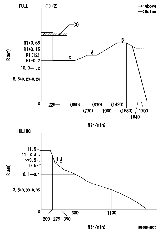
Test data Ex:
Governor adjustment

N:Pump speed
R:Rack position (mm)
(1)Torque cam stamping: T1
(2)Tolerance for racks not indicated: +-0.05mm.
(3)RACK LIMIT
----------
T1=K11
----------
----------
T1=K11
----------
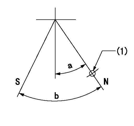
Speed control lever angle

F:Full speed
I:Idle
(1)Use the hole at R = aa
(2)Stopper bolt set position 'H'
----------
aa=100mm
----------
a=26.5deg+-5deg b=(46deg)+-3deg
----------
aa=100mm
----------
a=26.5deg+-5deg b=(46deg)+-3deg
Stop lever angle

N:Pump normal
S:Stop the pump.
(1)Use the hole at R = aa
----------
aa=28mm
----------
a=20deg+-5deg b=40deg+-5deg
----------
aa=28mm
----------
a=20deg+-5deg b=40deg+-5deg
Timing setting

(1)Pump vertical direction
(2)Position of timer's threaded hole at No 1 cylinder's beginning of injection
(3)-
(4)-
----------
----------
a=(60deg)
----------
----------
a=(60deg)
Information:
Intermittent Problems
Intermittent electronic problems are extremely difficult to troubleshoot, especially when there is no diagnostic code logged. Recreating the intermittent problem is the first logical step. However, when the problem only happens once a week, it may take a week to recreate the fault. It is not cost effective to drive around for hours hoping the problem will reoccur. Randomly changing parts may fix the problem but usually results in future downtime for the truck. The purpose of this section is to provide step-by-step procedures which mechanics can use to troubleshoot intermittent problems without extensive road testing and random parts changing. Two types of intermittent failures are as follows: Repeatable Intermittents - happen somewhat frequently (every 30 miles or several times an hour). Unrepeatable Intermittents - do not happen frequently (every 500 miles or possibly once a week).The mechanics time is best spent trying to recreate/isolate Repeatable Intermittents. However, trying to recreate/isolate an Unrepeatable Intermittent is not cost effective. Therefore, the first and most important step of isolating an intermittent problem is determining which type of intermittent it is. This should be done by questioning the driver and having he or she fill out the Driver Questionnaire which is supplied in this manual. Be sure to make copies of the questionnaire for future use. Finally, review the Test Status Checklist (if available) if the truck has been in a previous shop for the same repair. P-101 Intermittent Engine Speed or Speed Burps
The following procedure should only be used once the problem has definitely been determined to be Intermittent. Otherwise, refer to Section 2 of the 3406B Electronic Troubleshooting Guide, SENR3479, to isolate an Active problem. Complete Steps 2 through 11
Each step will eliminate one subsystem (complete all steps).Fill out a copy of the Unrepeatable Test Status Checklist at the back of this manual.Return the truck to service with copies of both the Driver Questionnaire and the Unrepeatable Test Status Checklist.Interview the driver once the truck returns.If the problem is gone, work backwards using the "Diagnosis and Action When Truck Returns" column to determine which step has eliminated the problem.