Information injection-pump assembly
ZEXEL
101606-9961
1016069961
NISSAN-DIESEL
16713Z6373
16713z6373
Rating:
Service parts 101606-9961 INJECTION-PUMP ASSEMBLY:
1.
_

7.
COUPLING PLATE
8.
_
9.
_
11.
Nozzle and Holder
16600-Z5665
12.
Open Pre:MPa(Kqf/cm2)
19.6{200}
15.
NOZZLE SET
Include in #1:
101606-9961
as INJECTION-PUMP ASSEMBLY
Include in #2:
104134-1071
as _
Cross reference number
ZEXEL
101606-9961
1016069961
NISSAN-DIESEL
16713Z6373
16713z6373
Zexel num
Bosch num
Firm num
Name
Calibration Data:
Adjustment conditions
Test oil
1404 Test oil ISO4113 or {SAEJ967d}
1404 Test oil ISO4113 or {SAEJ967d}
Test oil temperature
degC
40
40
45
Nozzle and nozzle holder
105780-8140
Bosch type code
EF8511/9A
Nozzle
105780-0000
Bosch type code
DN12SD12T
Nozzle holder
105780-2080
Bosch type code
EF8511/9
Opening pressure
MPa
17.2
Opening pressure
kgf/cm2
175
Injection pipe
Outer diameter - inner diameter - length (mm) mm 6-2-600
Outer diameter - inner diameter - length (mm) mm 6-2-600
Overflow valve
134424-1520
Overflow valve opening pressure
kPa
162
147
177
Overflow valve opening pressure
kgf/cm2
1.65
1.5
1.8
Tester oil delivery pressure
kPa
157
157
157
Tester oil delivery pressure
kgf/cm2
1.6
1.6
1.6
Direction of rotation (viewed from drive side)
Right R
Right R
Injection timing adjustment
Direction of rotation (viewed from drive side)
Right R
Right R
Injection order
1-4-2-6-
3-5
Pre-stroke
mm
3.4
3.35
3.45
Beginning of injection position
Drive side NO.1
Drive side NO.1
Difference between angles 1
Cal 1-4 deg. 60 59.5 60.5
Cal 1-4 deg. 60 59.5 60.5
Difference between angles 2
Cyl.1-2 deg. 120 119.5 120.5
Cyl.1-2 deg. 120 119.5 120.5
Difference between angles 3
Cal 1-6 deg. 180 179.5 180.5
Cal 1-6 deg. 180 179.5 180.5
Difference between angles 4
Cal 1-3 deg. 240 239.5 240.5
Cal 1-3 deg. 240 239.5 240.5
Difference between angles 5
Cal 1-5 deg. 300 299.5 300.5
Cal 1-5 deg. 300 299.5 300.5
Injection quantity adjustment
Adjusting point
-
Rack position
11.7
Pump speed
r/min
800
800
800
Average injection quantity
mm3/st.
71
69.4
72.6
Max. variation between cylinders
%
0
-3.5
3.5
Basic
*
Fixing the rack
*
Standard for adjustment of the maximum variation between cylinders
*
Injection quantity adjustment_02
Adjusting point
H
Rack position
9.5+-0.5
Pump speed
r/min
275
275
275
Average injection quantity
mm3/st.
10.5
8.7
12.3
Max. variation between cylinders
%
0
-10
10
Fixing the rack
*
Standard for adjustment of the maximum variation between cylinders
*
Injection quantity adjustment_03
Adjusting point
A
Rack position
R1(11.7)
Pump speed
r/min
800
800
800
Average injection quantity
mm3/st.
71
70
72
Basic
*
Fixing the lever
*
Injection quantity adjustment_04
Adjusting point
B
Rack position
R1+0.1
Pump speed
r/min
1500
1500
1500
Average injection quantity
mm3/st.
84
80
88
Fixing the lever
*
Injection quantity adjustment_05
Adjusting point
I
Rack position
-
Pump speed
r/min
100
100
100
Average injection quantity
mm3/st.
82
82
92
Fixing the lever
*
Rack limit
*
Timer adjustment
Pump speed
r/min
1200--
Advance angle
deg.
0
0
0
Remarks
Start
Start
Timer adjustment_02
Pump speed
r/min
1150
Advance angle
deg.
0.5
Timer adjustment_03
Pump speed
r/min
1500
Advance angle
deg.
6.5
6.2
6.8
Remarks
Finish
Finish
Test data Ex:
Governor adjustment
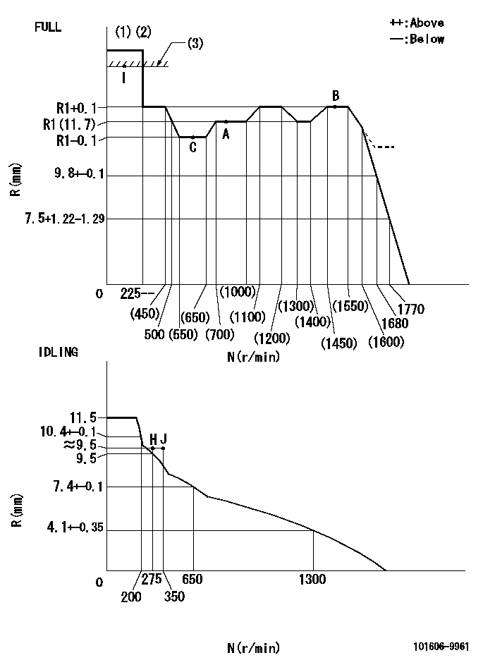
N:Pump speed
R:Rack position (mm)
(1)Torque cam stamping: T1
(2)Tolerance for racks not indicated: +-0.05mm.
(3)RACK LIMIT
----------
T1=J50
----------
----------
T1=J50
----------
Speed control lever angle

F:Full speed
I:Idle
(1)Use the hole at R = aa
(2)Stopper bolt set position 'H'
----------
aa=36mm
----------
a=20.5deg+-5deg b=36deg+-3deg
----------
aa=36mm
----------
a=20.5deg+-5deg b=36deg+-3deg
Stop lever angle

N:Pump normal
S:Stop the pump.
----------
----------
a=20deg+-5deg b=40deg+-5deg
----------
----------
a=20deg+-5deg b=40deg+-5deg
0000001501 RACK SENSOR
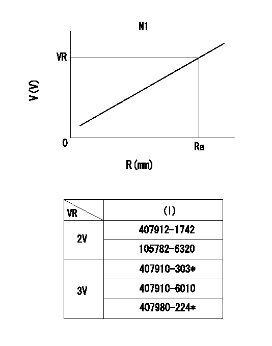
R:Rack position (mm)
V:Voltage (V)
After installing the rack sensor, confirm the output value (VR).
----------
N1=800r/min Ra=R1(11.7)mm VR=2.5+-0.01V
----------
----------
N1=800r/min Ra=R1(11.7)mm VR=2.5+-0.01V
----------
Timing setting

(1)Pump vertical direction
(2)Position of timer's threaded hole at No 1 cylinder's beginning of injection
(3)-
(4)-
----------
----------
a=(60deg)
----------
----------
a=(60deg)
Information:
Troubleshooting can be difficult. The Troublsehooting Index gives a list of possible problems. To make a repair to a problem, make reference to the cause and correction on the pages that follow.This list of problems, causes, and corrections will only give an indication of where a possible problem can be, and what repairs are needed. Normally, more or other repair work is needed beyond the recommendations in the list.Remember that a problem is not normally caused only by one part, but by the relation of one part with other parts. This list is only a guide and cannot give all possible problems and corrections. The serviceman must find the problem and its source, then make the necessary repairs. For each problem, a list of possible causes and corrections is given. The list of probable causes and corrections should be performed in numeric sequence.1. Engine Crankshaft Will Not Turn When Ignition Switch Is On2. Engine Hard To Or Will Not Start Engine Crankshaft Turns Too Slowly3. Engine Hard To Or Will Not Start Engine Crankshaft Turns Freely4. Engine Misfiring Or Running Rough5. Engine Stall At Low RPM6. Knock Or Miss At Idle7. Rough Idle8. Low Power9. Engine Speed Is Not Stable10. Engine Overspeeds On Start11. Too Much Vibration12. Loud Combustion Noise13. Valve Train Noise14. Oil In Cooling System15. Mechanical Noise (Knock) In Engine16. Fuel Consumption Too High17. Too Much Valve Lash18. Little Or No Valve Lash19. Oil At The Exhaust20. Engine Has Excessive Early Wear21. Coolant In Lubrication Oil22. Too Much Exhaust Smoke (Black Or Gray)23. Too Much Exhaust Smoke (White Or Blue)24. Engine Has Low Oil Pressure25. Engine Uses Too Much Lubrication Oil26. Above Normal Coolant Temperature27. Below Normal Coolant Temperature28. Exhaust Temperature Too High29. Starter Motor Does Not Turn30. Alternator Gives No Charge31. Alternator Charge Rate Is Low Or Not Regular32. Alternator Charge Too High33. Alternator Has Noise34. Fuel In Lubrication Oil35. Fuel In Coolant36. Loss Of Coolant37. Air Inlet Heater38. Soot In The Inlet Manifold39. Air In Fuel