Information injection-pump assembly
BOSCH
F 019 Z10 996
f019z10996
ZEXEL
101606-9791
1016069791
Rating:
Include in #1:
101401-7453
as _
Cross reference number
BOSCH
F 019 Z10 996
f019z10996
ZEXEL
101606-9791
1016069791
Zexel num
Bosch num
Firm num
Name
101606-9791
F 019 Z10 996
DPICO
INJECTION-PUMP ASSEMBLY
6D22 Q
6D22 Q
Calibration Data:
Adjustment conditions
Test oil
1404 Test oil ISO4113 or {SAEJ967d}
1404 Test oil ISO4113 or {SAEJ967d}
Test oil temperature
degC
40
40
45
Nozzle and nozzle holder
105780-8140
Bosch type code
EF8511/9A
Nozzle
105780-0000
Bosch type code
DN12SD12T
Nozzle holder
105780-2080
Bosch type code
EF8511/9
Opening pressure
MPa
17.2
Opening pressure
kgf/cm2
175
Injection pipe
Outer diameter - inner diameter - length (mm) mm 6-2-600
Outer diameter - inner diameter - length (mm) mm 6-2-600
Overflow valve
131424-5120
Overflow valve opening pressure
kPa
255
221
289
Overflow valve opening pressure
kgf/cm2
2.6
2.25
2.95
Tester oil delivery pressure
kPa
157
157
157
Tester oil delivery pressure
kgf/cm2
1.6
1.6
1.6
Direction of rotation (viewed from drive side)
Right R
Right R
Injection timing adjustment
Direction of rotation (viewed from drive side)
Right R
Right R
Injection order
1-5-3-6-
2-4
Pre-stroke
mm
4.5
4.45
4.55
Beginning of injection position
Governor side NO.1
Governor side NO.1
Difference between angles 1
Cal 1-5 deg. 60 59.5 60.5
Cal 1-5 deg. 60 59.5 60.5
Difference between angles 2
Cal 1-3 deg. 120 119.5 120.5
Cal 1-3 deg. 120 119.5 120.5
Difference between angles 3
Cal 1-6 deg. 180 179.5 180.5
Cal 1-6 deg. 180 179.5 180.5
Difference between angles 4
Cyl.1-2 deg. 240 239.5 240.5
Cyl.1-2 deg. 240 239.5 240.5
Difference between angles 5
Cal 1-5 deg. 300 299.5 300.5
Cal 1-5 deg. 300 299.5 300.5
Injection quantity adjustment
Adjusting point
-
Rack position
9.6
Pump speed
r/min
700
700
700
Each cylinder's injection qty
mm3/st.
112
109.2
114.8
Basic
*
Fixing the rack
*
Standard for adjustment of the maximum variation between cylinders
*
Injection quantity adjustment_02
Adjusting point
C
Rack position
6.8+-0.5
Pump speed
r/min
450
450
450
Each cylinder's injection qty
mm3/st.
20
17
23
Fixing the rack
*
Standard for adjustment of the maximum variation between cylinders
*
Injection quantity adjustment_03
Adjusting point
A
Rack position
R1(9.6)
Pump speed
r/min
700
700
700
Average injection quantity
mm3/st.
112
111
113
Basic
*
Fixing the lever
*
Injection quantity adjustment_04
Adjusting point
E
Rack position
-
Pump speed
r/min
100
100
100
Average injection quantity
mm3/st.
125
85
165
Fixing the lever
*
Remarks
After startup boost setting
After startup boost setting
Injection quantity adjustment_05
Adjusting point
F
Rack position
7.3+-0.5
Pump speed
r/min
335
335
335
Average injection quantity
mm3/st.
16
14.5
17.5
Fixing the rack
*
Timer adjustment
Pump speed
r/min
950--
Advance angle
deg.
0
0
0
Remarks
Start
Start
Timer adjustment_02
Pump speed
r/min
900
Advance angle
deg.
0.5
Timer adjustment_03
Pump speed
r/min
1150
Advance angle
deg.
4.5
4
5
Remarks
Finish
Finish
Test data Ex:
Governor adjustment
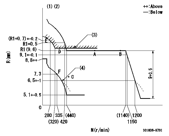
N:Pump speed
R:Rack position (mm)
(1)Microswitch not operating at delivery.
(2)Tolerance for racks not indicated: +-0.05mm.
(3)Excess fuel setting for starting: SXL (N = N1)
(4)Damper spring setting: DL
----------
SXL=(R1+0.1)+0.2mm N1=350r/min DL=6-0.2mm
----------
----------
SXL=(R1+0.1)+0.2mm N1=350r/min DL=6-0.2mm
----------
Speed control lever angle

F:Full speed
----------
----------
a=(0.5deg)+-5deg
----------
----------
a=(0.5deg)+-5deg
0000000901
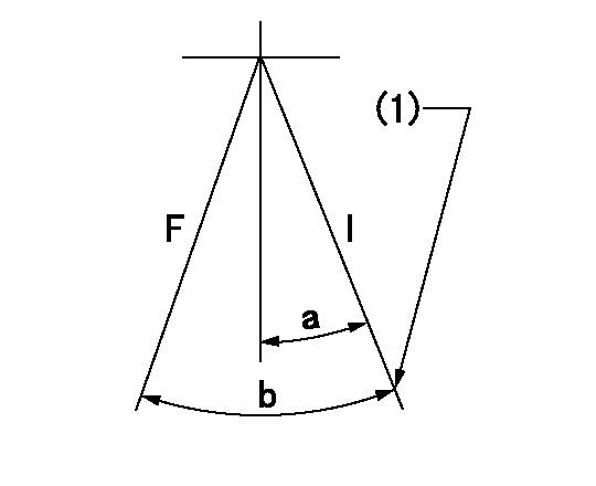
F:Full load
I:Idle
(1)Stopper bolt setting
----------
----------
a=7.5deg+-5deg b=16.5deg+-3deg
----------
----------
a=7.5deg+-5deg b=16.5deg+-3deg
Stop lever angle
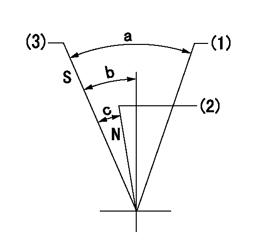
N:Engine manufacturer's normal use
S:Stop the pump.
(1)Free (at delivery)
(2)Rack position = aa
(3)Rack position = bb, set the stopper bolt.
----------
aa=13.5mm bb=6-0.5mm
----------
a=(52deg) b=30deg+-5deg c=24deg+-5deg
----------
aa=13.5mm bb=6-0.5mm
----------
a=(52deg) b=30deg+-5deg c=24deg+-5deg
Timing setting

(1)Pump vertical direction
(2)Coupling's key groove position at No 1 cylinder's beginning of injection
(3)B.T.D.C.: aa
(4)-
----------
aa=15deg
----------
a=(7deg)
----------
aa=15deg
----------
a=(7deg)
Information:
Right Side (6 Cylinder Shown)(1) Depth that cup plugs are installed (measured from block face to top edge of plug) ... 1.25 0.25 mm (.049 .010 in)(2) Distance all sleeves extend from top face ... 14 2 mm (.55 .08 in)(3) Distance two large dowels extend from rear face ... 12.0 0.5 mm (.47 .02 in)(4) Distance two small dowels extend from rear face ... 8.0 0.5 mm (.31 .02 in)(5) Distance all dowels extend from front face ... 8.0 0.5 mm (.31 .02 in)
View A-A (Rear Face)(6) Bores in block for all camshaft bearings except front bearing ... 69.000 0.038 mm (2.7165 .0015 in)(7) Locate bearing oil hole for all camshaft bearings (except front bearing) at top of bore.
Front Face(8) Bore in block for front camshaft bearing ... 70.000 0.025 mm (2.7559 .0010 in)(9) Front camshaft bearing joint location.(10) Front camshaft bearing oil hole. Install front camshaft bearing with bearing oil hole (10) aligned with oil hole in block and bearing joint (9) positioned as shown.(11) Width of main bearing cap ... 159.995 0.020 mm (6.2990 .0008 in) Width of cylinder block for main bearing cap ... 160.000 0.018 mm (6.2992 .0007 in)(12) Bore in block for main bearings ... 95.000 0.013 mm (3.7402 .0005 in)(13) Main bearing cap bolts. Install as follows: Install bearing caps with sequence number to the right, 1 through 5 (for 4 cylinder) or 1 through 7 (for 6 cylinder), front to rear.a. Before assembly, put 2P2506 Thread Lubricant on the bolt threads and washer face.b. Tighten both bolts of each bearing cap to a torque of ... 54 7 N m (40 5 lb ft)c. Then tighten bolts an additional ... 90 5 degrees (1/4 turn)(14) Location of bearing cap sequence number.(15) Dimension from centerline of crankshaft bore to pan rail ... 110.00 mm (4.331 in)(16) Dimension from centerline of crankshaft bore to top of block ... 322.00 .017 mm (12.677 .0007 in)(17) Cylinder bore size ... 105.025 .025 mm (4.1348 .0010 in) Bore size must be checked with a 4C4377 Cylinder Head Stress Plate and gasket installed. Refer to Installation Of 7C6208 Cylinder Sleeve, Special Instruction Form No. SEHS9047. (18) Piston cooling jet. Check piston cooling jets by inserting a 1.3 mm (.05 in) diameter drill rod into jet. Rod must pass through a 5.0 mm (.20 in) diameter circle in location (A) and a 13 mm (.51 in) diameter circle in location (B). Dimension (C) is 25.9 mm (1.02 in). Dimension (D) is 33.4 mm (1.31 in). Dimension (E) is 26.95 mm (1.061 in). Dimension (F) is 9.8 mm (.39 in). Dimension (G) is 50 mm (2.0 in). Distance four sleeves (19) extend from side face ... 5.0 0.5 mm (.20 .02 in)
Have questions with 101606-9791?
Group cross 101606-9791 ZEXEL
Nissan-Diesel
Dpico
101606-9791
F 019 Z10 996
INJECTION-PUMP ASSEMBLY
6D22
6D22