Information injection-pump assembly
BOSCH
9 400 613 053
9400613053
ZEXEL
101606-9461
1016069461

Rating:
Service parts 101606-9461 INJECTION-PUMP ASSEMBLY:
1.
_
7.
COUPLING PLATE
8.
_
9.
_
11.
Nozzle and Holder
12.
Open Pre:MPa(Kqf/cm2)
14.7{150}/21.6{220}
15.
NOZZLE SET
Cross reference number
BOSCH
9 400 613 053
9400613053
ZEXEL
101606-9461
1016069461
Zexel num
Bosch num
Firm num
Name
101606-9461
9 400 613 053
DPICO
INJECTION-PUMP ASSEMBLY
EM100 Q
EM100 Q
Calibration Data:
Adjustment conditions
Test oil
1404 Test oil ISO4113 or {SAEJ967d}
1404 Test oil ISO4113 or {SAEJ967d}
Test oil temperature
degC
40
40
45
Nozzle and nozzle holder
105780-8140
Bosch type code
EF8511/9A
Nozzle
105780-0000
Bosch type code
DN12SD12T
Nozzle holder
105780-2080
Bosch type code
EF8511/9
Opening pressure
MPa
17.2
Opening pressure
kgf/cm2
175
Injection pipe
Outer diameter - inner diameter - length (mm) mm 6-2-600
Outer diameter - inner diameter - length (mm) mm 6-2-600
Overflow valve
131424-5720
Overflow valve opening pressure
kPa
255
221
289
Overflow valve opening pressure
kgf/cm2
2.6
2.25
2.95
Tester oil delivery pressure
kPa
157
157
157
Tester oil delivery pressure
kgf/cm2
1.6
1.6
1.6
Direction of rotation (viewed from drive side)
Right R
Right R
Injection timing adjustment
Direction of rotation (viewed from drive side)
Right R
Right R
Injection order
1-4-2-6-
3-5
Pre-stroke
mm
4.3
4.25
4.35
Beginning of injection position
Drive side NO.1
Drive side NO.1
Difference between angles 1
Cal 1-4 deg. 60 59.5 60.5
Cal 1-4 deg. 60 59.5 60.5
Difference between angles 2
Cyl.1-2 deg. 120 119.5 120.5
Cyl.1-2 deg. 120 119.5 120.5
Difference between angles 3
Cal 1-6 deg. 180 179.5 180.5
Cal 1-6 deg. 180 179.5 180.5
Difference between angles 4
Cal 1-3 deg. 240 239.5 240.5
Cal 1-3 deg. 240 239.5 240.5
Difference between angles 5
Cal 1-5 deg. 300 299.5 300.5
Cal 1-5 deg. 300 299.5 300.5
Injection quantity adjustment
Adjusting point
A
Rack position
7.7
Pump speed
r/min
800
800
800
Average injection quantity
mm3/st.
96
94
98
Max. variation between cylinders
%
0
-3
3
Basic
*
Fixing the lever
*
Injection quantity adjustment_02
Adjusting point
B
Rack position
(7.9)
Pump speed
r/min
1350
1350
1350
Average injection quantity
mm3/st.
105
99
111
Max. variation between cylinders
%
0
-4
4
Fixing the lever
*
Injection quantity adjustment_03
Adjusting point
E
Rack position
5.6+-0.5
Pump speed
r/min
225
225
225
Average injection quantity
mm3/st.
15
13
17
Max. variation between cylinders
%
0
-15
15
Fixing the rack
*
Injection quantity adjustment_04
Adjusting point
F
Rack position
-
Pump speed
r/min
100
100
100
Average injection quantity
mm3/st.
115
75
155
Fixing the lever
*
Remarks
After startup boost setting
After startup boost setting
Timer adjustment
Pump speed
r/min
1130--
Advance angle
deg.
0
0
0
Remarks
Start
Start
Timer adjustment_02
Pump speed
r/min
1080
Advance angle
deg.
0.5
Timer adjustment_03
Pump speed
r/min
1330
Advance angle
deg.
4.5
4
5
Remarks
Finish
Finish
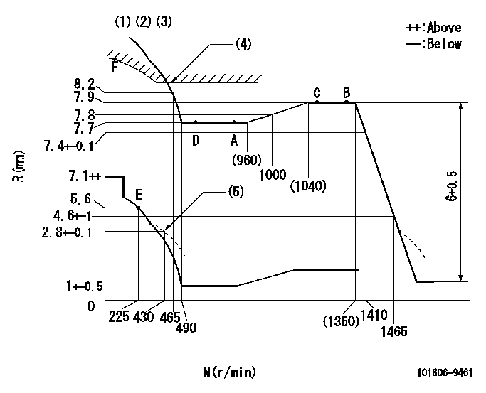
Test data Ex:
Governor adjustment

N:Pump speed
R:Rack position (mm)
(1)Lever ratio: RT
(2)Target shim dimension: TH
(3)Tolerance for racks not indicated: +-0.05mm.
(4)Excess fuel setting for starting: SXL (N = N1)
(5)Damper spring setting
----------
RT=0.8 TH=1.5mm SXL=8.9+-0.1mm N1=400r/min
----------
----------
RT=0.8 TH=1.5mm SXL=8.9+-0.1mm N1=400r/min
----------
Speed control lever angle

F:Full speed
----------
----------
a=(5.5deg)+-5deg
----------
----------
a=(5.5deg)+-5deg
0000000901

F:Full load
I:Idle
(1)Stopper bolt setting
----------
----------
a=23deg+-5deg b=35.5deg+-3deg
----------
----------
a=23deg+-5deg b=35.5deg+-3deg
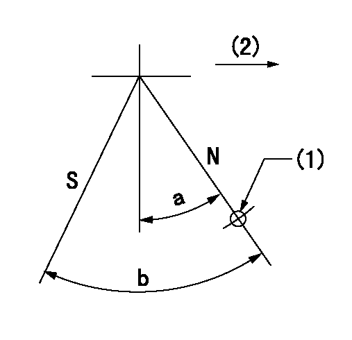
Stop lever angle

N:Pump normal
S:Stop the pump.
(1)Use the pin at R = aa
(2)Drive side
----------
aa=20mm
----------
a=40deg+-5deg b=71deg+-5deg
----------
aa=20mm
----------
a=40deg+-5deg b=71deg+-5deg
Timing setting

(1)Pump vertical direction
(2)Coupling's key groove position at No 1 cylinder's beginning of injection
(3)B.T.D.C.: aa
(4)-
----------
aa=15deg
----------
a=(60deg)
----------
aa=15deg
----------
a=(60deg)
Information:
Location of Screwdriver While Holding BellcrankK. Rotate the timing position sensor bellcrank clock wise by inserting the No. 2 Phillips screwdriver between the arm of the bellcrank in contact with the timing position sensor until the screwdriver can be inserted into the hole in the cover to hold the bellcrank in position.
Hold Timing Position Sensor Bellcrank In PositionL. Install the gasket and timing advance housing (4).M. Remove the screwdriver to allow the bellcrank to contact the power piston.9. Check the timing sensor position calibration as described in P-531: Timing Position Sensor/Calibration.10. Install the timing solenoid (BTM). Make sure the arm of the timing solenoid is in the center groove of the control spool collar.11. Install the timing advance position sensor cover (3).P-540: Idle Shutdown Timer
System Operation
The idle shutdown timer is a feature which helps improve fuel consumption by limiting idling time. The timer may be programmed to shut down the idling engine after a period of time. This "shutdown time" is a customer specified parameter, and may be programmed for any period from 3 to 60 minutes. Programming the time to zero disables the idle shutdown timer.The timer is activated when the parking brake is set, vehicle speed is zero, and the engine is not under load. Ninety seconds before the programmed time is reached, the diagnostic lamp will begin to flash rapidly. If the driver moves the clutch pedal or brake pedal during this 90 second period, the timer will be overridden and is reset. A diagnostic code 71-00 will be set when the driver overrides the timer using the clutch or brake.If the timer is activated and allowed to shutdown the engine, then a code 71-01 will be set. Code 71-01 merely records the event and does not indicate a fault in PEEC III. If any of the codes for vehicle speed are Active, the idle shutdown timer will not operate.Diagnostic Codes
Functional Test
P-541: Multi-Torque
System Operation
Multi-Torque is an optional feature available with certain PEEC III engines. The feature is available only in certain personality modules.The 310 Multi-Torque provides an otherwise standard 310 hp PEEC III engine with two different torque curves. In all gears except top gear, the engine performs as a standard 310 hp PEEC III. In top gear, however, the engine is provided with the torque of a standard 310 hp at 1800 rpm, but with the peak torque of 350 hp at 1150 rpm (see the following illustrations).PEEC III determines whether the vehicle is in top gear by sensing the ratio of engine speed to vehicle speed. If the ratio of engine speed/vehicle speed is less than 26.6, the engine will perform like a standard 310 hp PEEC III.The 350 Multi-Torque works just like the 310Multi-Torque, except for two key differences. First, the multi-torque curve provides the engine with the standard 350 hp torque at 1800 rpm, and with the peak torque of a 400 hp at 1200 rpm (see the following illustration). Second, the multi-torque is in effect in the top two gears,
Have questions with 101606-9461?
Group cross 101606-9461 ZEXEL
Nissan-Diesel
Hyundai
Nissan-Diesel
Dpico
101606-9461
9 400 613 053
INJECTION-PUMP ASSEMBLY
EM100
EM100