Information injection-pump assembly
BOSCH
9 400 619 555
9400619555
ZEXEL
101606-9460
1016069460

Rating:
Service parts 101606-9460 INJECTION-PUMP ASSEMBLY:
1.
_
7.
COUPLING PLATE
8.
_
9.
_
11.
Nozzle and Holder
12.
Open Pre:MPa(Kqf/cm2)
14.7{150}/21.6{220}
15.
NOZZLE SET
Cross reference number
BOSCH
9 400 619 555
9400619555
ZEXEL
101606-9460
1016069460
Zexel num
Bosch num
Firm num
Name
Calibration Data:
Adjustment conditions
Test oil
1404 Test oil ISO4113 or {SAEJ967d}
1404 Test oil ISO4113 or {SAEJ967d}
Test oil temperature
degC
40
40
45
Nozzle and nozzle holder
105780-8140
Bosch type code
EF8511/9A
Nozzle
105780-0000
Bosch type code
DN12SD12T
Nozzle holder
105780-2080
Bosch type code
EF8511/9
Opening pressure
MPa
17.2
Opening pressure
kgf/cm2
175
Injection pipe
Outer diameter - inner diameter - length (mm) mm 6-2-600
Outer diameter - inner diameter - length (mm) mm 6-2-600
Overflow valve
131424-5720
Overflow valve opening pressure
kPa
255
221
289
Overflow valve opening pressure
kgf/cm2
2.6
2.25
2.95
Tester oil delivery pressure
kPa
157
157
157
Tester oil delivery pressure
kgf/cm2
1.6
1.6
1.6
Direction of rotation (viewed from drive side)
Right R
Right R
Injection timing adjustment
Direction of rotation (viewed from drive side)
Right R
Right R
Injection order
1-4-2-6-
3-5
Pre-stroke
mm
4.3
4.25
4.35
Beginning of injection position
Drive side NO.1
Drive side NO.1
Difference between angles 1
Cal 1-4 deg. 60 59.5 60.5
Cal 1-4 deg. 60 59.5 60.5
Difference between angles 2
Cyl.1-2 deg. 120 119.5 120.5
Cyl.1-2 deg. 120 119.5 120.5
Difference between angles 3
Cal 1-6 deg. 180 179.5 180.5
Cal 1-6 deg. 180 179.5 180.5
Difference between angles 4
Cal 1-3 deg. 240 239.5 240.5
Cal 1-3 deg. 240 239.5 240.5
Difference between angles 5
Cal 1-5 deg. 300 299.5 300.5
Cal 1-5 deg. 300 299.5 300.5
Injection quantity adjustment
Adjusting point
A
Rack position
7.7
Pump speed
r/min
800
800
800
Average injection quantity
mm3/st.
96
94
98
Max. variation between cylinders
%
0
-3
3
Basic
*
Fixing the lever
*
Injection quantity adjustment_02
Adjusting point
B
Rack position
7.9+-0.5
Pump speed
r/min
1350
1350
1350
Average injection quantity
mm3/st.
105
99
111
Max. variation between cylinders
%
0
-4
4
Fixing the lever
*
Injection quantity adjustment_03
Adjusting point
E
Rack position
5.6+-0.5
Pump speed
r/min
225
225
225
Average injection quantity
mm3/st.
15
13
17
Max. variation between cylinders
%
0
-15
15
Fixing the rack
*
Injection quantity adjustment_04
Adjusting point
F
Rack position
-
Pump speed
r/min
100
100
100
Average injection quantity
mm3/st.
115
75
155
Fixing the lever
*
Remarks
After startup boost setting
After startup boost setting
Timer adjustment
Pump speed
r/min
1130--
Advance angle
deg.
0
0
0
Remarks
Start
Start
Timer adjustment_02
Pump speed
r/min
1080
Advance angle
deg.
0.5
Timer adjustment_03
Pump speed
r/min
1330
Advance angle
deg.
4.5
4
5
Remarks
Finish
Finish
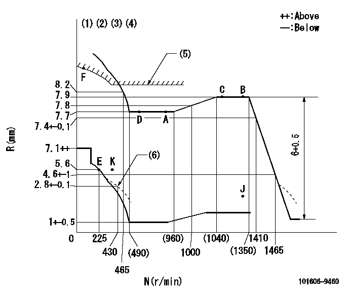
Test data Ex:
Governor adjustment

N:Pump speed
R:Rack position (mm)
(1)Lever ratio: RT
(2)Target shim dimension: TH
(3)Tolerance for racks not indicated: +-0.05mm.
(4)Microswitch not operating at delivery.
(5)Excess fuel setting for starting: SXL (N = N1)
(6)Damper spring setting
----------
RT=0.8 TH=1.5mm SXL=8.9+-0.1mm N1=400r/min
----------
----------
RT=0.8 TH=1.5mm SXL=8.9+-0.1mm N1=400r/min
----------
Speed control lever angle

F:Full speed
----------
----------
a=(5.5deg)+-5deg
----------
----------
a=(5.5deg)+-5deg
0000000901

F:Full load
I:Idle
(1)Stopper bolt setting
----------
----------
a=23deg+-5deg b=33.5deg+-3deg
----------
----------
a=23deg+-5deg b=33.5deg+-3deg
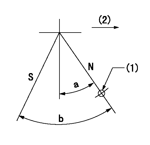
Stop lever angle

N:Pump normal
S:Stop the pump.
(1)Use the pin at R = aa
(2)Drive side
----------
aa=20mm
----------
a=40deg+-5deg b=71deg+-5deg
----------
aa=20mm
----------
a=40deg+-5deg b=71deg+-5deg
Timing setting

(1)Pump vertical direction
(2)Coupling's key groove position at No 1 cylinder's beginning of injection
(3)B.T.D.C.: aa
(4)-
----------
aa=15deg
----------
a=(60deg)
----------
aa=15deg
----------
a=(60deg)
Information:
ACTIVE Diagnostic Codes
Diagnostic codes are used by the PEEC III system to warn the vehicle operator of a problem and indicate to the service technician the nature of the problem. Some codes are used only to record an event, and do not indicate problems.An ACTIVE Diagnostic code represents a problem that should be investigated and corrected AS SOON AS POSSIBLE. Repairing the cause of an ACTIVE code will cause the code to be cleared from the ACTIVE Diagnostic Code screen.When an ACTIVE code is generated, the PEEC III lamp will turn ON and remain ON, blinking every five seconds. If the condition generating the fault occurs only for a brief moment, the lamp will go OFF after five seconds and the fault will be LOGGED. After a problem has been investigated and corrected, the related diagnostic code should be cleared from memory.ACTIVE codes may be viewed using either of the electronic service tools (ECAP or DDT), and may also be viewed using the diagnostic lamp and cruise control switches. The diagnostic lamp should not be confused with the warning lamp which is used with PEEC III engine protection.Using The ECAP Or DDT To Display ACTIVE Codes
A. With key OFF, install an ECAP or DDT into the PEEC III system.B. Turn key ON (engine does not need to be started to view codes).C. Refer to the Operating Manual and Special Instructions for the service tool (listed under PEEC III Service Tools) to read the code(s). On the ECAP, the display menu will direct you to the proper screen to display diagnostic messages similar to the example below.Using The Cruise Control Switches To Display ACTIVE Codes:
A. Turn key ON (engine does not need to be started to view codes).B. The PEEC III Diagnostic Lamp will turn ON for five seconds, blink OFF for 1/10 second, turn ON again for five seconds, then OFF for five seconds. At the end of that time, the lamp will begin to flash the first number of the two-digit code (count the flashes). After two seconds OFF, then it will flash the second digit. If two or more codes are present, they will follow the first after a few seconds and be displayed in the same manner.C. Active Diagnostic codes may be displayed at any time by using cruise control switches. With key ON or engine running, turn the cruise control ON/OFF switch to OFF, and move the SET/RESUME switch to RESUME position. Once the codes begin to flash the switch may be released. The PEEC III Diagnostic Lamp will flash out all the codes that are currently active, or intermittent codes that have occurred since the key was turned on. LOGGED Diagnostic Codes
When an ECM generates a diagnostic code, it usually logs the code in permanent memory within the ECM. The time the code occurred (in hours on the internal diagnostic clock) is logged along with the code. The logged codes can then be later retrieved or erased using an ECAP or DDT service