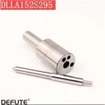
Information injection-pump assembly
ZEXEL
101606-9250
1016069250
Rating:
Service parts 101606-9250 INJECTION-PUMP ASSEMBLY:
1.
_
6.
COUPLING PLATE
7.
COUPLING PLATE
8.
_
9.
_
11.
Nozzle and Holder
12.
Open Pre:MPa(Kqf/cm2)
21.6{220}
15.
NOZZLE SET
Include in #1:
101606-9250
as INJECTION-PUMP ASSEMBLY
Cross reference number
ZEXEL
101606-9250
1016069250
Zexel num
Bosch num
Firm num
Name
Calibration Data:
Adjustment conditions
Test oil
1404 Test oil ISO4113 or {SAEJ967d}
1404 Test oil ISO4113 or {SAEJ967d}
Test oil temperature
degC
40
40
45
Nozzle and nozzle holder
105780-8140
Bosch type code
EF8511/9A
Nozzle
105780-0000
Bosch type code
DN12SD12T
Nozzle holder
105780-2080
Bosch type code
EF8511/9
Opening pressure
MPa
17.2
Opening pressure
kgf/cm2
175
Injection pipe
Outer diameter - inner diameter - length (mm) mm 6-2-600
Outer diameter - inner diameter - length (mm) mm 6-2-600
Overflow valve
131424-5520
Overflow valve opening pressure
kPa
255
221
289
Overflow valve opening pressure
kgf/cm2
2.6
2.25
2.95
Tester oil delivery pressure
kPa
157
157
157
Tester oil delivery pressure
kgf/cm2
1.6
1.6
1.6
Direction of rotation (viewed from drive side)
Left L
Left L
Injection timing adjustment
Direction of rotation (viewed from drive side)
Left L
Left L
Injection order
1-5-3-6-
2-4
Pre-stroke
mm
3.2
3.15
3.25
Beginning of injection position
Governor side NO.1
Governor side NO.1
Difference between angles 1
Cal 1-5 deg. 60 59.5 60.5
Cal 1-5 deg. 60 59.5 60.5
Difference between angles 2
Cal 1-3 deg. 120 119.5 120.5
Cal 1-3 deg. 120 119.5 120.5
Difference between angles 3
Cal 1-6 deg. 180 179.5 180.5
Cal 1-6 deg. 180 179.5 180.5
Difference between angles 4
Cyl.1-2 deg. 240 239.5 240.5
Cyl.1-2 deg. 240 239.5 240.5
Difference between angles 5
Cal 1-4 deg. 300 299.5 300.5
Cal 1-4 deg. 300 299.5 300.5
Injection quantity adjustment
Adjusting point
-
Rack position
10.8
Pump speed
r/min
700
700
700
Each cylinder's injection qty
mm3/st.
73
71.2
74.8
Basic
*
Fixing the rack
*
Standard for adjustment of the maximum variation between cylinders
*
Injection quantity adjustment_02
Adjusting point
H
Rack position
9.5+-0.5
Pump speed
r/min
275
275
275
Each cylinder's injection qty
mm3/st.
11
9.5
12.5
Fixing the rack
*
Standard for adjustment of the maximum variation between cylinders
*
Injection quantity adjustment_03
Adjusting point
A
Rack position
R1(10.8)
Pump speed
r/min
700
700
700
Average injection quantity
mm3/st.
73
72
74
Basic
*
Fixing the lever
*
Injection quantity adjustment_04
Adjusting point
B
Rack position
R1-0.35
Pump speed
r/min
1450
1450
1450
Average injection quantity
mm3/st.
80.5
76.5
84.5
Fixing the lever
*
Injection quantity adjustment_05
Adjusting point
I
Rack position
-
Pump speed
r/min
100
100
100
Average injection quantity
mm3/st.
73
63
83
Fixing the lever
*
Rack limit
*
Timer adjustment
Pump speed
r/min
1250--
Advance angle
deg.
0
0
0
Remarks
Start
Start
Timer adjustment_02
Pump speed
r/min
1200
Advance angle
deg.
0.8
Timer adjustment_03
Pump speed
r/min
1500
Advance angle
deg.
5
4.5
5.5
Remarks
Finish
Finish
Test data Ex:
Governor adjustment
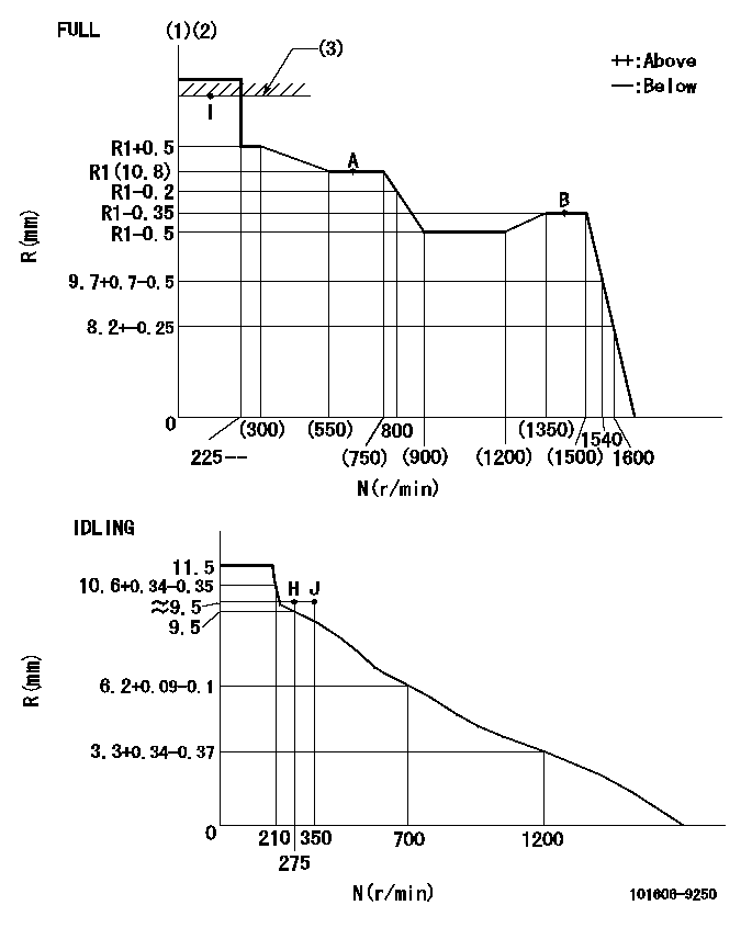
N:Pump speed
R:Rack position (mm)
(1)Torque cam stamping: T1
(2)Tolerance for racks not indicated: +-0.05mm.
(3)RACK LIMIT
----------
T1=H85
----------
----------
T1=H85
----------
Speed control lever angle
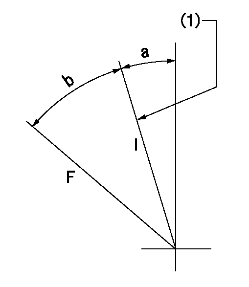
F:Full speed
I:Idle
(1)Stopper bolt set position 'H'
----------
----------
a=18.5deg+-5deg b=(38deg)+-3deg
----------
----------
a=18.5deg+-5deg b=(38deg)+-3deg
Stop lever angle
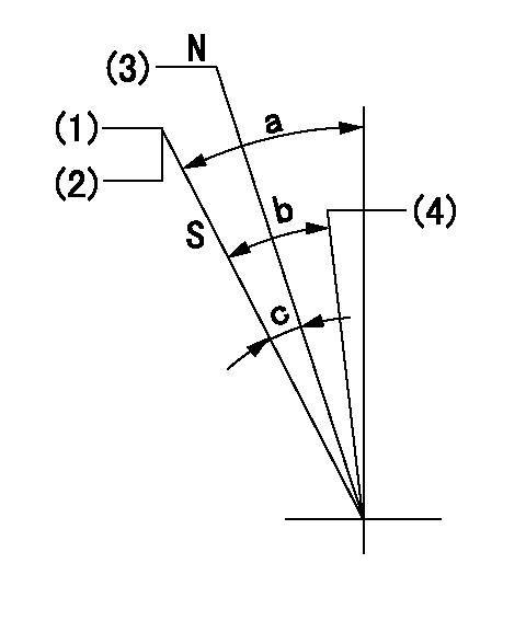
N:Engine manufacturer's normal use
S:Stop the pump.
(1)Set the stopper bolt at pump speed = aa and rack position = bb (non-injection rack position) and confirm non-injection. Then confirm non-injection at rack position cc.
(2)After setting the stopper bolt, confirm non-injection at speed = dd.
(3)Rack position = approximately ee.
(4)Free (at delivery)
----------
aa=1450r/min bb=6.7-0.5mm cc=(8.3)mm dd=275r/min ee=17.4mm
----------
a=38.5deg+-5deg b=(27deg) c=17deg+-5deg
----------
aa=1450r/min bb=6.7-0.5mm cc=(8.3)mm dd=275r/min ee=17.4mm
----------
a=38.5deg+-5deg b=(27deg) c=17deg+-5deg
0000001501 MICRO SWITCH
Adjustment of the micro-switch
Adjust the bolt to obtain the following lever position when the micro-switch is ON.
(1)Speed N1
(2)Rack position Ra
----------
N1=400r/min Ra=9.2+-0.1mm
----------
----------
N1=400r/min Ra=9.2+-0.1mm
----------
Timing setting

(1)Pump vertical direction
(2)Position of timer's tooth at No 1 cylinder's beginning of injection
(3)B.T.D.C.: aa
(4)-
----------
aa=14deg
----------
a=(0deg)
----------
aa=14deg
----------
a=(0deg)
Information:
High Gear Turn On Speed:
Vehicle Speed where "High Gear RPM Limit" turns on. This must be matched to the specific drive train for best performance. Minimum 30 mphMaximum 127 mphDefault 127 mphEngine Parameters
Rating Number:
Number of rating within horsepower family. The Personality Module defines the horsepower family (such as 325 hp) and may contain several ratings within that family. The rating number defines which rating is used (such as 325 hp @ 1900 rpm or 325 hp @ 2100 rpm) within the family.Top Engine Limit:
Maximum engine rpm when the engine is under load. The engine will still achieve rated rpm under no load conditions. TEL is dependent upon the RATING number, with some RATING numbers allowing no or little variation as specified below. Minimum 1300 rpmMaximum 3000 rpmDefault 1820 rpmLow Idle RPM:
Minimum engine rpm. Minimum 600 rpmMaximum 750 rpmDefault 700 rpmIdle Shutdown Time:
Time (in minutes) that engine will idle before shutting down. Engine will only shutdown if 3176 sees no engine load, no vehicle speed, and the parking brake is set. If this parameter is programmed to zero, this feature is disabled and the engine will idle until the key switch is turned OFF. this feature does not shut down vehicle power - the ECM and vehicle remain powered. Minimum 3 min.Maximum 60 min.Default 0 min.Vehicle ID:
Identification of the vehicle assigned by the customer. Used only for customer reference: not required by the ECM.Engine Protection Parameters
Engine Protection Mode:
Determines the level of action taken by the ECM in response to a potentially engine damaging condition recognized by the Caterpillar Coolant Temperature, Oil Pressure, or OEM Coolant Level (if installed and enabled) Sensors. Default Alternative OFFAlternative DERATEAlternative SHUTDOWNCoolant Level Sensor Enable/Disable:
This feature is not available on Personality Modules for engines before OCT91. The ECAP will show NOT INSTALLED on the Customer Programmable Parameters screen for pre-OCT91 Personality Modules. If a newer Personality Module is replacing an older Personality Module, this feature must be DISABLED.Determines if the ECM monitors the Coolant Level Sensor inputs.Default ENABLEDAlternative DISABLEDPasswords
Factory Passwords
Factory passwords are required to perform each of the following four functions:1. Program a New ECM When an ECM is replaced, the System Configuration Parameters must be programmed into the new ECM. These parameters are protected by factory passwords.2. Rerate Engine to another Engine Family This requires changing the Personality Module Code, which is protected by factory passwords.3. Read Customer Passwords If the owner loses his customer passwords, he will not be able to program customer parameters. Using factory passwords, one can read customer passwords, then use those customer passwords to program customer parameters.4. Clear Certain Diagnostic Codes Only Diagnostic Code 190-00 (Engine Overspeed Warning) requires factory passwords to clear once it is logged. Certain other codes require customer passwords. The majority of logged codes require no passwords to clear.Since factory passwords contain alphabetic characters, only the ECAP may perform these functions. The DDT cannot because it does not have alphabetic character keys.To obtain factory passwords, proceed as if you already had the password. At some
