Information injection-pump assembly
BOSCH
9 400 615 556
9400615556
ZEXEL
101606-9200
1016069200
NISSAN-DIESEL
16713Z6064
16713z6064
Rating:
Service parts 101606-9200 INJECTION-PUMP ASSEMBLY:
1.
_
7.
COUPLING PLATE
8.
_
9.
_
11.
Nozzle and Holder
16600-Z5600
12.
Open Pre:MPa(Kqf/cm2)
19.6{200}
15.
NOZZLE SET
Cross reference number
BOSCH
9 400 615 556
9400615556
ZEXEL
101606-9200
1016069200
NISSAN-DIESEL
16713Z6064
16713z6064
Zexel num
Bosch num
Firm num
Name
101606-9200
9 400 615 556
16713Z6064 NISSAN-DIESEL
INJECTION-PUMP ASSEMBLY
FE6A K 14BE INJECTION PUMP ASSY PE6A PE
FE6A K 14BE INJECTION PUMP ASSY PE6A PE
Calibration Data:
Adjustment conditions
Test oil
1404 Test oil ISO4113 or {SAEJ967d}
1404 Test oil ISO4113 or {SAEJ967d}
Test oil temperature
degC
40
40
45
Nozzle and nozzle holder
105780-8140
Bosch type code
EF8511/9A
Nozzle
105780-0000
Bosch type code
DN12SD12T
Nozzle holder
105780-2080
Bosch type code
EF8511/9
Opening pressure
MPa
17.2
Opening pressure
kgf/cm2
175
Injection pipe
Outer diameter - inner diameter - length (mm) mm 6-2-600
Outer diameter - inner diameter - length (mm) mm 6-2-600
Overflow valve
131424-1520
Overflow valve opening pressure
kPa
157
123
191
Overflow valve opening pressure
kgf/cm2
1.6
1.25
1.95
Tester oil delivery pressure
kPa
157
157
157
Tester oil delivery pressure
kgf/cm2
1.6
1.6
1.6
Direction of rotation (viewed from drive side)
Right R
Right R
Injection timing adjustment
Direction of rotation (viewed from drive side)
Right R
Right R
Injection order
1-4-2-6-
3-5
Pre-stroke
mm
3
2.95
3.05
Beginning of injection position
Drive side NO.1
Drive side NO.1
Difference between angles 1
Cal 1-4 deg. 60 59.5 60.5
Cal 1-4 deg. 60 59.5 60.5
Difference between angles 2
Cyl.1-2 deg. 120 119.5 120.5
Cyl.1-2 deg. 120 119.5 120.5
Difference between angles 3
Cal 1-6 deg. 180 179.5 180.5
Cal 1-6 deg. 180 179.5 180.5
Difference between angles 4
Cal 1-3 deg. 240 239.5 240.5
Cal 1-3 deg. 240 239.5 240.5
Difference between angles 5
Cal 1-5 deg. 300 299.5 300.5
Cal 1-5 deg. 300 299.5 300.5
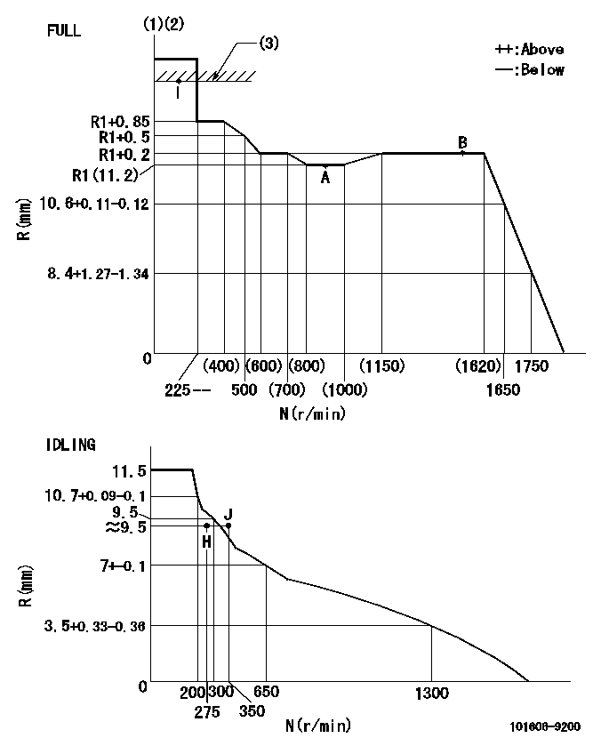
Injection quantity adjustment
Adjusting point
-
Rack position
11.2
Pump speed
r/min
900
900
900
Average injection quantity
mm3/st.
61.6
60
63.2
Max. variation between cylinders
%
0
-3.5
3.5
Basic
*
Fixing the rack
*
Standard for adjustment of the maximum variation between cylinders
*
Injection quantity adjustment_02
Adjusting point
H
Rack position
9.5+-0.5
Pump speed
r/min
275
275
275
Average injection quantity
mm3/st.
8.7
6.9
10.5
Max. variation between cylinders
%
0
-10
10
Fixing the rack
*
Standard for adjustment of the maximum variation between cylinders
*
Injection quantity adjustment_03
Adjusting point
A
Rack position
R1(11.2)
Pump speed
r/min
900
900
900
Average injection quantity
mm3/st.
61.6
60.6
62.6
Basic
*
Fixing the lever
*
Injection quantity adjustment_04
Adjusting point
B
Rack position
R1+0.2
Pump speed
r/min
1500
1500
1500
Average injection quantity
mm3/st.
76.1
72.1
80.1
Fixing the lever
*
Injection quantity adjustment_05
Adjusting point
I
Rack position
-
Pump speed
r/min
100
100
100
Average injection quantity
mm3/st.
81
81
91
Fixing the lever
*
Rack limit
*
Timer adjustment
Pump speed
r/min
(1140)
Advance angle
deg.
0
0
0
Remarks
Start
Start
Timer adjustment_02
Pump speed
r/min
1500
Advance angle
deg.
4
3.5
4.5
Remarks
Finish
Finish
Test data Ex:
Governor adjustment
N:Pump speed
R:Rack position (mm)
(1)Torque cam stamping: T1
(2)Tolerance for racks not indicated: +-0.05mm.
(3)RACK LIMIT
----------
T1=H02
----------
----------
T1=H02
----------
Speed control lever angle

F:Full speed
I:Idle
(1)Use the hole at R = aa
(2)Stopper bolt set position 'H'
----------
aa=36mm
----------
a=27.5deg+-5deg b=40deg+-3deg
----------
aa=36mm
----------
a=27.5deg+-5deg b=40deg+-3deg
Stop lever angle

N:Pump normal
S:Stop the pump.
(1)Use the pin at R = aa
----------
aa=42mm
----------
a=40deg+-5deg b=27deg+-5deg
----------
aa=42mm
----------
a=40deg+-5deg b=27deg+-5deg
Timing setting

(1)Pump vertical direction
(2)Position of timer's threaded hole at No 1 cylinder's beginning of injection
(3)-
(4)-
----------
----------
a=(60deg)
----------
----------
a=(60deg)
Information:
Turn the engine to (TDC) top center compression stroke for the No. 1 piston and install crankshaft flywheel timing pin. This will help when timing the camshaft when installing.
Wire used to hold cam roller followers up off camshaft. It is not necessary to remove the cylinder head. With the cylinder head in place, just wire the cam roller followers up off the camshaft and then remove the camshaft. 1. Remove camshaft retainer bolt (1) and remove camshaft assembly (2). The following steps are for the installation of the camshaft assembly.
Typical Example When installing the camshaft, rotating it both clockwise and counter clockwise directions will help prevent it from binding in the bearing bores.2. Put engine oil on the lobes and journals of the camshaft. Carefully install the camshaft. When installing the camshaft, be sure the number one cylinder is at (TDC) top dead center of the compression stroke with the timing pin installed in the flywheel. Camshaft timing is very important. Cam gear timing marks must line up with idler gear timing marks as illustrated. For more information about timing of engine, refer to Specifications module, Form No. SENR3908.
Camshaft Timing3. With the camshaft properly timed and positioned, install retaining bolt (1). Tighten bolt (1) to a torque of 48 7 N m (37 5 lb ft). Remove the wire that was used to hold the cam roller followers up off the camshaft.End By:a. install fuel transfer pumpb. install front coverc. install front pulley and damperd. install fuel injectorse. install rocker arm assemblies and push rodsDisassembly & Assembly of Camshaft And Gear Assembly
Start By:a. remove camshaft assembly 1. Wrap camshaft portion of camshaft and gear assembly (1) with paper towels to protect the camshaft from being damaged. 2. Remove six bolts (2). Remove timing/speed sensor ring gear (3). The timing/speed ring gear is located on gear (4) by dowel (6). Care must be taken not to damage timing/speed sensor ring gear (3) when removing. Using the prybar, work around the ring gear and pry the ring gear off a little at a time.
Care must be taken not to allow the camshaft to fall to the floor when pressing it from the gear. Also be sure that a camshaft lobe does not catch on the press plates.
3. Place camshaft and gear assembly (1) in a press. Press camshaft (5) from gear (4). The following steps are for the assembly of the camshaft and the gear assembly. 4. To install gear (4) on camshaft (5), place gear in the oven at 300°C (572°F) for 30 minutes and then install. Be sure the woodruff key is properly aligned and the gear is flush with the camshaft flange. 5. Align timing gear sensor ring gear (3) with dowel (6). "Front" is marked and visible when installing timing/speed ring gear sensor. Care must be taken not to damage the timing/speed sensor ring gear when installing. Using a mallet tap around the ring gear and drive it on a little at a
Have questions with 101606-9200?
Group cross 101606-9200 ZEXEL
Nissan-Diesel
101606-9200
9 400 615 556
16713Z6064
INJECTION-PUMP ASSEMBLY
FE6A
FE6A