Information injection-pump assembly
ZEXEL
101606-9071
1016069071
NISSAN-DIESEL
16713Z5521
16713z5521

Rating:
Cross reference number
ZEXEL
101606-9071
1016069071
NISSAN-DIESEL
16713Z5521
16713z5521
Zexel num
Bosch num
Firm num
Name
101606-9071
16713Z5521 NISSAN-DIESEL
INJECTION-PUMP ASSEMBLY
FE6B * K
FE6B * K
Calibration Data:
Adjustment conditions
Test oil
1404 Test oil ISO4113 or {SAEJ967d}
1404 Test oil ISO4113 or {SAEJ967d}
Test oil temperature
degC
40
40
45
Nozzle and nozzle holder
105780-8140
Bosch type code
EF8511/9A
Nozzle
105780-0000
Bosch type code
DN12SD12T
Nozzle holder
105780-2080
Bosch type code
EF8511/9
Opening pressure
MPa
17.2
Opening pressure
kgf/cm2
175
Injection pipe
Outer diameter - inner diameter - length (mm) mm 6-2-600
Outer diameter - inner diameter - length (mm) mm 6-2-600
Overflow valve
134424-1520
Overflow valve opening pressure
kPa
162
147
177
Overflow valve opening pressure
kgf/cm2
1.65
1.5
1.8
Tester oil delivery pressure
kPa
157
157
157
Tester oil delivery pressure
kgf/cm2
1.6
1.6
1.6
Direction of rotation (viewed from drive side)
Right R
Right R
Injection timing adjustment
Direction of rotation (viewed from drive side)
Right R
Right R
Injection order
1-4-2-6-
3-5
Pre-stroke
mm
3.4
3.35
3.45
Beginning of injection position
Drive side NO.1
Drive side NO.1
Difference between angles 1
Cal 1-4 deg. 60 59.5 60.5
Cal 1-4 deg. 60 59.5 60.5
Difference between angles 2
Cyl.1-2 deg. 120 119.5 120.5
Cyl.1-2 deg. 120 119.5 120.5
Difference between angles 3
Cal 1-6 deg. 180 179.5 180.5
Cal 1-6 deg. 180 179.5 180.5
Difference between angles 4
Cal 1-3 deg. 240 239.5 240.5
Cal 1-3 deg. 240 239.5 240.5
Difference between angles 5
Cal 1-5 deg. 300 299.5 300.5
Cal 1-5 deg. 300 299.5 300.5
Injection quantity adjustment
Adjusting point
-
Rack position
12
Pump speed
r/min
800
800
800
Average injection quantity
mm3/st.
74
72.4
75.6
Max. variation between cylinders
%
0
-3.5
3.5
Basic
*
Fixing the rack
*
Standard for adjustment of the maximum variation between cylinders
*
Injection quantity adjustment_02
Adjusting point
H
Rack position
9.5+-0.5
Pump speed
r/min
275
275
275
Average injection quantity
mm3/st.
10.4
8.6
12.2
Max. variation between cylinders
%
0
-10
10
Fixing the rack
*
Standard for adjustment of the maximum variation between cylinders
*
Injection quantity adjustment_03
Adjusting point
A
Rack position
R1(12)
Pump speed
r/min
800
800
800
Average injection quantity
mm3/st.
74
73
75
Basic
*
Fixing the lever
*
Injection quantity adjustment_04
Adjusting point
B
Rack position
R1+0.05
Pump speed
r/min
1500
1500
1500
Average injection quantity
mm3/st.
85.5
81.5
89.5
Fixing the lever
*
Injection quantity adjustment_05
Adjusting point
I
Rack position
-
Pump speed
r/min
100
100
100
Average injection quantity
mm3/st.
80
80
90
Fixing the lever
*
Rack limit
*
Timer adjustment
Pump speed
r/min
-
Advance angle
deg.
0.5
Remarks
Measure the actual speed.
Measure the actual speed.
Timer adjustment_02
Pump speed
r/min
-
Advance angle
deg.
6.5
6.5
6.5
Remarks
Measure the actual speed, stop
Measure the actual speed, stop
Test data Ex:
Governor adjustment
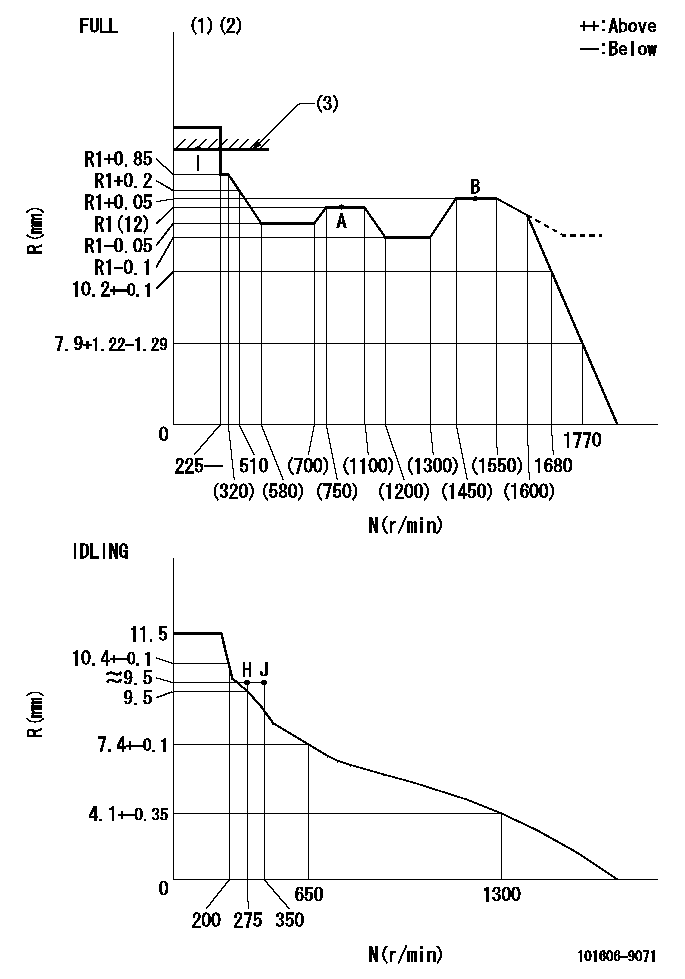
N:Pump speed
R:Rack position (mm)
(1)Torque cam stamping: T1
(2)Tolerance for racks not indicated: +-0.05mm.
(3)RACK LIMIT
----------
T1=G08
----------
----------
T1=G08
----------
Speed control lever angle

F:Full speed
I:Idle
(1)Use the hole at R = aa
(2)Stopper bolt set position 'H'
----------
aa=36mm
----------
a=26.5deg+-5deg b=36deg+-3deg
----------
aa=36mm
----------
a=26.5deg+-5deg b=36deg+-3deg
Stop lever angle

N:Pump normal
S:Stop the pump.
----------
----------
a=20deg+-5deg b=40deg+-5deg
----------
----------
a=20deg+-5deg b=40deg+-5deg
0000001501 RACK SENSOR
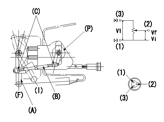
V1:Supply voltage
Vf:Full side output voltage
Vi:Idle side output voltage
(a) Speed lever
(B) Link
(c) Nut
(F) Full
(I) Idle
(P) Potentiometer
1. Load sensor adjustment
(1)Apply DC5 = V1 voltage between potentiometer connector terminals (1) ~ (3) and measure the output voltage between (1) ~ (2).
(2)Move the speed lever (A) until it contacts the full side stopper bolt and then turn the link (B) to adjust the potentiometer (P)'s output voltage to Vf.
(3)Confirm that the speed lever (A) turns smoothly between idle (I) and Full (F) and tighten the nut (C). (Tightening torque: 3.4 ~ 4.9 N.m {0.35 ~ 0.5 kgf.m})
(4)Move the speed lever (A) several times between idle (I) and full (F) and confirm that the voltage is Vf when it contacts the full side stopper bolt and Vi when it contacts the idle side stopper bolt.
----------
V1=5+-0.02V Vf=4.8++V Vi=0.5+0.4-0.3V
----------
----------
V1=5+-0.02V Vf=4.8++V Vi=0.5+0.4-0.3V
----------
Timing setting

(1)Pump vertical direction
(2)Position of timer's threaded hole at No 1 cylinder's beginning of injection
(3)-
(4)-
----------
----------
a=(60deg)
----------
----------
a=(60deg)
Information:
1. Once all connections have been checked, energize the system.A) The RED indicator light should come on. This indicates that the control is 'OFF'.*... If the LO indicator light is 'ON', it indicates an open connection on the BLUE output wire going to the center solenoid.... If the MED indicator light is 'ON', it indicates an open connection on the YELLOW output wire going to the front and/or rear solenoids*If the RED light starts to flash: This indicates that there is an open connection on the output.If an open connection occurs, insure that there is a good connection at the solenoid, and at the output of the control module. If there is still a problem remove the harness connections on the 002299 terminal leadout. Measure the resistance of the solenoid at the 002299 terminal leadout on the Jake Brake housing (+ probe on the 002299 terminal, - probe to ground). The ohmmeter should read between 7 and 14 ohms. If it does not, replace the solenoid. If the problem still occurs, replace the suspected output wire, and insure a good connection
Have questions with 101606-9071?
Group cross 101606-9071 ZEXEL
Hyundai
Nissan-Diesel
Nissan-Diesel
101606-9071
16713Z5521
INJECTION-PUMP ASSEMBLY
FE6B
FE6B