Information injection-pump assembly
ZEXEL
101606-9070
1016069070

Rating:
Cross reference number
ZEXEL
101606-9070
1016069070
Zexel num
Bosch num
Firm num
Name
101606-9070
INJECTION-PUMP ASSEMBLY
Calibration Data:
Adjustment conditions
Test oil
1404 Test oil ISO4113 or {SAEJ967d}
1404 Test oil ISO4113 or {SAEJ967d}
Test oil temperature
degC
40
40
45
Nozzle and nozzle holder
105780-8140
Bosch type code
EF8511/9A
Nozzle
105780-0000
Bosch type code
DN12SD12T
Nozzle holder
105780-2080
Bosch type code
EF8511/9
Opening pressure
MPa
17.2
Opening pressure
kgf/cm2
175
Injection pipe
Outer diameter - inner diameter - length (mm) mm 6-2-600
Outer diameter - inner diameter - length (mm) mm 6-2-600
Overflow valve
134424-1520
Overflow valve opening pressure
kPa
162
147
177
Overflow valve opening pressure
kgf/cm2
1.65
1.5
1.8
Tester oil delivery pressure
kPa
157
157
157
Tester oil delivery pressure
kgf/cm2
1.6
1.6
1.6
Direction of rotation (viewed from drive side)
Right R
Right R
Injection timing adjustment
Direction of rotation (viewed from drive side)
Right R
Right R
Injection order
1-4-2-6-
3-5
Pre-stroke
mm
3.4
3.35
3.45
Beginning of injection position
Drive side NO.1
Drive side NO.1
Difference between angles 1
Cal 1-4 deg. 60 59.5 60.5
Cal 1-4 deg. 60 59.5 60.5
Difference between angles 2
Cyl.1-2 deg. 120 119.5 120.5
Cyl.1-2 deg. 120 119.5 120.5
Difference between angles 3
Cal 1-6 deg. 180 179.5 180.5
Cal 1-6 deg. 180 179.5 180.5
Difference between angles 4
Cal 1-3 deg. 240 239.5 240.5
Cal 1-3 deg. 240 239.5 240.5
Difference between angles 5
Cal 1-5 deg. 300 299.5 300.5
Cal 1-5 deg. 300 299.5 300.5
Injection quantity adjustment
Adjusting point
-
Rack position
12.3
Pump speed
r/min
800
800
800
Average injection quantity
mm3/st.
79.3
77.7
80.9
Max. variation between cylinders
%
0
-3.5
3.5
Basic
*
Fixing the rack
*
Standard for adjustment of the maximum variation between cylinders
*
Injection quantity adjustment_02
Adjusting point
H
Rack position
9.5+-0.5
Pump speed
r/min
275
275
275
Average injection quantity
mm3/st.
10.4
8.6
12.2
Max. variation between cylinders
%
0
-10
10
Fixing the rack
*
Standard for adjustment of the maximum variation between cylinders
*
Injection quantity adjustment_03
Adjusting point
A
Rack position
R1(12.3)
Pump speed
r/min
800
800
800
Average injection quantity
mm3/st.
79.3
78.3
80.3
Basic
*
Fixing the lever
*
Injection quantity adjustment_04
Adjusting point
B
Rack position
R1+0.05
Pump speed
r/min
1500
1500
1500
Average injection quantity
mm3/st.
91
87
95
Fixing the lever
*
Injection quantity adjustment_05
Adjusting point
I
Rack position
-
Pump speed
r/min
100
100
100
Average injection quantity
mm3/st.
80
80
90
Fixing the lever
*
Rack limit
*
Timer adjustment
Pump speed
r/min
1200--
Advance angle
deg.
0
0
0
Remarks
Start
Start
Timer adjustment_02
Pump speed
r/min
1150
Advance angle
deg.
0.5
Timer adjustment_03
Pump speed
r/min
1500
Advance angle
deg.
6.5
6.2
6.8
Remarks
Finish
Finish
Test data Ex:
Governor adjustment
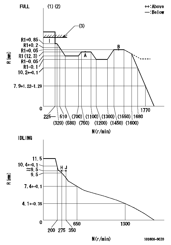
N:Pump speed
R:Rack position (mm)
(1)Torque cam stamping: T1
(2)Tolerance for racks not indicated: +-0.05mm.
(3)RACK LIMIT
----------
T1=G08
----------
----------
T1=G08
----------
Speed control lever angle

F:Full speed
I:Idle
(1)Use the hole at R = aa
(2)Stopper bolt set position 'H'
----------
aa=36mm
----------
a=26.5deg+-5deg b=36deg+-3deg
----------
aa=36mm
----------
a=26.5deg+-5deg b=36deg+-3deg
Stop lever angle

N:Pump normal
S:Stop the pump.
----------
----------
a=20deg+-5deg b=40deg+-5deg
----------
----------
a=20deg+-5deg b=40deg+-5deg
0000001501 RACK SENSOR
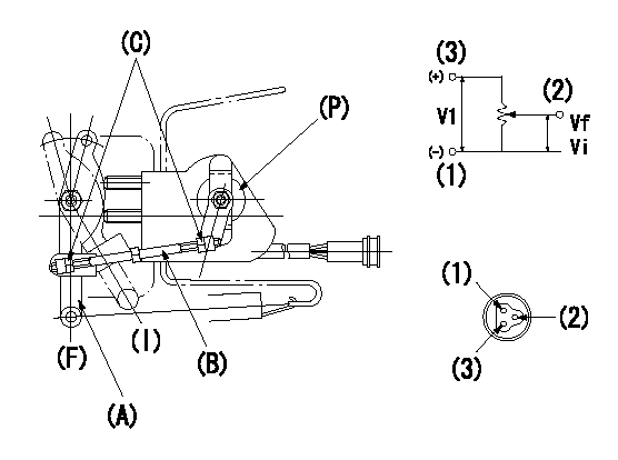
V1:Supply voltage
Vf:Full side output voltage
Vi:Idle side output voltage
(a) Speed lever
(B) Link
(c) Nut
(F) Full
(I) Idle
(P) Potentiometer
1. Load sensor adjustment
(1)Apply DC5 = V1 voltage between potentiometer connector terminals (1) ~ (3) and measure the output voltage between (1) ~ (2).
(2)Move the speed lever (A) until it contacts the full side stopper bolt and then turn the link (B) to adjust the potentiometer (P)'s output voltage to Vf.
(3)Confirm that the speed lever (A) turns smoothly between idle (I) and Full (F) and tighten the nut (C). (Tightening torque: 3.4 ~ 4.9 N.m {0.35 ~ 0.5 kgf.m})
(4)Move the speed lever (A) several times between idle (I) and full (F) and confirm that the voltage is Vf when it contacts the full side stopper bolt and Vi when it contacts the idle side stopper bolt.
----------
V1=5+-0.02V Vf=4.8++V Vi=0.5+0.4-0.3V
----------
----------
V1=5+-0.02V Vf=4.8++V Vi=0.5+0.4-0.3V
----------
Timing setting

(1)Pump vertical direction
(2)Position of timer's threaded hole at No 1 cylinder's beginning of injection
(3)-
(4)-
----------
----------
a=(60deg)
----------
----------
a=(60deg)
Information:
1. Disconnect plug P8 from receptacle J8. The locking ring helps identify P8 from J8. Check the connections for damaged wires or pins and corrosion. Also check that the pins are at the proper height in the connector. Check that the wires and pins are tight in the connectors by pulling (slightly) on each wire of each connector (including the breakout "T").2. Install 8T8695 Adapter (nine pin breakout "T") between J8 and P8. Twist the locking rings to secure the connections.3. Connect the voltmeter as shown. Check for the appropriate voltages between the lettered "T" pins as explained in Steps 4 through 8.4. Pin A (+) to pin B (ground) system voltage should be approximately 12 volts DC with key on (no accessories). Minimum voltage is 11.0 volts DC. While cranking the voltage should be 8 to 12 volts DC. Diagnosis - Using the truck wiring schematic, check wires A and B and connections from J8 through the truck wiring harness back to the battery terminals for proper voltage.5. If the voltage check between pins A and B on P8 is less than 11.0 volts with the key on, check the voltage drop from pin B of the J8 connector to the negative battery post while cranking. For this test, the common lead (black) should be connected to the negative battery post first. Then place the positive (red) lead into pin B. (Pin B is chassis ground.) Voltage should be less than .5 volts DC when cranking. Diagnosis - If voltage drop is greater than .5 volts DC, check wire B and connections (including the battery post connections) from J8 to battery negative.6. Pin C to pin B: For best accuracy, a service tool [3176 (7X1055) DDT, or (8T8697) ECAP] should be used for this test to measure the pulse width modulated signal (see Electronic Troubleshooting, 3176 Diesel Truck Engine, Form No. SENR3913). If engine deceleration occurs too quickly (1.5 seconds or less), the retarder status cannot be accurately monitored by a service tool. Retarder status should then be monitored during a vehicle road test.* The throttle must be adjusted properly (must have less than 7% throttle at low idle).* All OEM wires and connectors to the retarder device must be connected.* With the cruise control off and truck in neutral, increase the engine speed to high idle by depressing the throttle pedal to maximum position.* Voltage should be 4 volts DC. Quickly release the throttle and allow the engine to return to the low idle position.* During the engine deceleration from high idle to 950 rpm, voltage should be approximately 1 volt DC. (Do not depress the clutch pedal during this procedure.) Diagnosis - Check the retarder enable circuit, using the truck wiring schematic, from Pin C (P8) to the retarder device (Jake brake or exhaust brake).7. Pin F to Pin B:(Equipment supplied with the engine monitoring option module).* 1 to 4 volts DC with the key on and warning buzzer on (warning buzzer sounds for
Have questions with 101606-9070?
Group cross 101606-9070 ZEXEL
Hyundai
Nissan-Diesel
101606-9070
INJECTION-PUMP ASSEMBLY