Information injection-pump assembly
ZEXEL
101606-9050
1016069050
NISSAN-DIESEL
16713Z5972
16713z5972
Rating:
Cross reference number
ZEXEL
101606-9050
1016069050
NISSAN-DIESEL
16713Z5972
16713z5972
Zexel num
Bosch num
Firm num
Name
Calibration Data:
Adjustment conditions
Test oil
1404 Test oil ISO4113 or {SAEJ967d}
1404 Test oil ISO4113 or {SAEJ967d}
Test oil temperature
degC
40
40
45
Nozzle and nozzle holder
105780-8140
Bosch type code
EF8511/9A
Nozzle
105780-0000
Bosch type code
DN12SD12T
Nozzle holder
105780-2080
Bosch type code
EF8511/9
Opening pressure
MPa
17.2
Opening pressure
kgf/cm2
175
Injection pipe
Outer diameter - inner diameter - length (mm) mm 6-2-600
Outer diameter - inner diameter - length (mm) mm 6-2-600
Overflow valve
134424-1420
Overflow valve opening pressure
kPa
162
147
177
Overflow valve opening pressure
kgf/cm2
1.65
1.5
1.8
Tester oil delivery pressure
kPa
157
157
157
Tester oil delivery pressure
kgf/cm2
1.6
1.6
1.6
Direction of rotation (viewed from drive side)
Right R
Right R
Injection timing adjustment
Direction of rotation (viewed from drive side)
Right R
Right R
Injection order
1-4-2-6-
3-5
Pre-stroke
mm
3.7
3.65
3.75
Beginning of injection position
Drive side NO.1
Drive side NO.1
Difference between angles 1
Cal 1-4 deg. 60 59.5 60.5
Cal 1-4 deg. 60 59.5 60.5
Difference between angles 2
Cyl.1-2 deg. 120 119.5 120.5
Cyl.1-2 deg. 120 119.5 120.5
Difference between angles 3
Cal 1-6 deg. 180 179.5 180.5
Cal 1-6 deg. 180 179.5 180.5
Difference between angles 4
Cal 1-3 deg. 240 239.5 240.5
Cal 1-3 deg. 240 239.5 240.5
Difference between angles 5
Cal 1-5 deg. 300 299.5 300.5
Cal 1-5 deg. 300 299.5 300.5
Injection quantity adjustment
Adjusting point
-
Rack position
12.6
Pump speed
r/min
800
800
800
Average injection quantity
mm3/st.
80.1
78.5
81.7
Max. variation between cylinders
%
0
-3.5
3.5
Basic
*
Fixing the rack
*
Standard for adjustment of the maximum variation between cylinders
*
Injection quantity adjustment_02
Adjusting point
H
Rack position
9.5+-0.5
Pump speed
r/min
275
275
275
Average injection quantity
mm3/st.
11.5
9.7
13.3
Max. variation between cylinders
%
0
-10
10
Fixing the rack
*
Standard for adjustment of the maximum variation between cylinders
*
Injection quantity adjustment_03
Adjusting point
A
Rack position
R1(12.6)
Pump speed
r/min
800
800
800
Average injection quantity
mm3/st.
80.1
79.1
81.1
Basic
*
Fixing the lever
*
Injection quantity adjustment_04
Adjusting point
B
Rack position
R1(12.6)
Pump speed
r/min
1500
1500
1500
Average injection quantity
mm3/st.
92.7
88.7
96.7
Fixing the lever
*
Injection quantity adjustment_05
Adjusting point
C
Rack position
R1-0.2
Pump speed
r/min
600
600
600
Average injection quantity
mm3/st.
68.2
65
71.4
Fixing the lever
*
Injection quantity adjustment_06
Adjusting point
I
Rack position
-
Pump speed
r/min
100
100
100
Average injection quantity
mm3/st.
83
83
93
Fixing the lever
*
Rack limit
*
Timer adjustment
Pump speed
r/min
(1130)
Advance angle
deg.
0
0
0
Remarks
Measure speed (beginning of operation).
Measure speed (beginning of operation).
Timer adjustment_02
Pump speed
r/min
1200
Advance angle
deg.
1
0.5
1.5
Timer adjustment_03
Pump speed
r/min
1500
Advance angle
deg.
5.5
5.2
5.8
Remarks
Finish
Finish
Test data Ex:
Governor adjustment
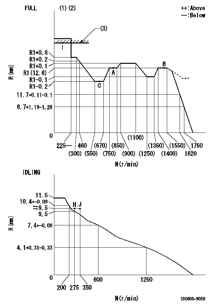
N:Pump speed
R:Rack position (mm)
(1)Torque cam stamping: T1
(2)Tolerance for racks not indicated: +-0.05mm.
(3)RACK LIMIT
----------
T1=H05
----------
----------
T1=H05
----------
Speed control lever angle
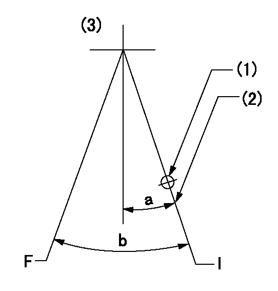
F:Full speed
I:Idle
(1)Use the hole at R = aa
(2)Stopper bolt set position 'H'
(3)Bottom lever
----------
aa=39mm
----------
a=26.5deg+-5deg b=38deg+-3deg
----------
aa=39mm
----------
a=26.5deg+-5deg b=38deg+-3deg
Stop lever angle
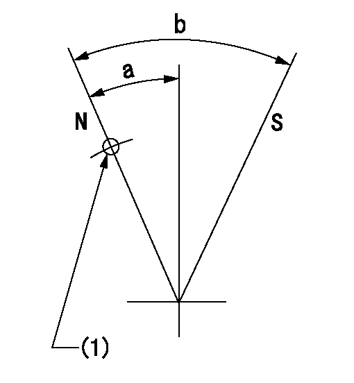
N:Pump normal
S:Stop the pump.
(1)Use the pin at R = aa
----------
aa=42mm
----------
a=20deg+-5deg b=40deg+-5deg
----------
aa=42mm
----------
a=20deg+-5deg b=40deg+-5deg
0000001501 LEVER
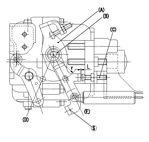
(a) Speed lever
(B) Accelerator lever
(C) Accelerator lever stopper bolt
(D) Full speed side
(E) idle side
1. Accelerator lever setting method
With speed lever at idle position, from point S contact
Back off the accelerator lever stopper bolt L and set. (Turn bolt L turns and set.)
----------
----------
r=33mm L=1+0.5mm
----------
----------
r=33mm L=1+0.5mm
Timing setting

(1)Pump vertical direction
(2)Position of timer's threaded hole at No 1 cylinder's beginning of injection
(3)-
(4)-
----------
----------
a=(60deg)
----------
----------
a=(60deg)
Information:
1. Disconnect plug P11 from receptacle J11. The locking ring helps identify P11 from J11. Check the connections for damaged wires or pins and corrosion. Also check that the pins are at the proper height in the connector. Check that the wires and pins are tight in the connectors by pulling (slightly) on each wire of each connector (including the breakout "T").2. Install 8T8726 Adapter (three pin breakout "T") between J11 and P11. Twist the locking rings to secure the connections.3. Connect the voltmeter as shown. Check for the appropriate voltages between the lettered "T" pins as explained in Steps 4 through 6.4. Pin A (+) to pin B (ground) system voltage should be approximately 12 volts DC with key on (no accessories). Minimum voltage is 11.0 volts DC. While cranking, the voltage should be between 8-12 volts DC. Diagnosis - Using the truck wiring schematic, check wires A and B and connections from J11 through the truck wiring harness back to the battery terminals for proper voltage.5. If the voltage check between pins A and B is less than 11.0 volts with the key on, check the voltage drop from pin B to the negative battery post while cranking. For this test, the common lead (black) should be connected to the negative battery post first. Then place the positive (red) lead into pin B. (Pin B is chassis ground.) Voltage should be less than .5 volts DC when cranking. Diagnosis - If the voltage drop is greater than .5 volts DC, check wire B and connections (including the battery post connections) from J11 to battery negative. Follow the truck wiring schematic to trace the electrical path from J11 to chassis ground.6. Pin C to pin B:* Less than 1.0 volt DC with the key on and the foot pedal in the low idle position.* More than 3.5 volts DC with the foot pedal in the high idle position. Diagnosis - If pin A to pin B voltage is proper and the voltage from pin C to pin B does not vary from low idle to high idle, check J11 pin C and socket connection. Check for broken throttle linkage from foot pedal to throttle position sensor. (Throttle position sensor needs adjustment or replacement. See Electronic Troubleshooting, 3176 Diesel Truck Engine, Form No. SENR3913, or the Testing and Adjusting section in Systems Operation, Testing and Adjusting, 3176 Diesel Truck Engine, Form No. SENR3909. Caterpillar supplied part, but initial adjustment is OEM responsibility.)7. Disconnect breakout "T" and reconnect P11 to J11. Secure the locking ring.If problem has not been resolved, proceed to the next connector to be tested as shown in the Operational Problem Chart section.If this is the last connector to be checked for the operational problem being investigated:* The problem could lie within the customer specified parameters. Check with the 3176 (7X1055) DDT or the (8T8697) ECAP.* Check the throttle linkage for 100% throttle signal with the 3176 (7X1055) DDT or (8T8697) ECAP.* Review connector tests again.