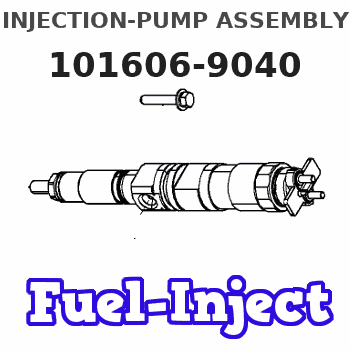
Information injection-pump assembly
ZEXEL
101606-9040
1016069040
NISSAN-DIESEL
16713Z5968
16713z5968

Rating:
Service parts 101606-9040 INJECTION-PUMP ASSEMBLY:
1.
_
7.
COUPLING PLATE
8.
_
9.
_
11.
Nozzle and Holder
16600-Z5608
12.
Open Pre:MPa(Kqf/cm2)
19.6{200}
15.
NOZZLE SET
Cross reference number
ZEXEL
101606-9040
1016069040
NISSAN-DIESEL
16713Z5968
16713z5968
Zexel num
Bosch num
Firm num
Name
Calibration Data:
Adjustment conditions
Test oil
1404 Test oil ISO4113 or {SAEJ967d}
1404 Test oil ISO4113 or {SAEJ967d}
Test oil temperature
degC
40
40
45
Nozzle and nozzle holder
105780-8140
Bosch type code
EF8511/9A
Nozzle
105780-0000
Bosch type code
DN12SD12T
Nozzle holder
105780-2080
Bosch type code
EF8511/9
Opening pressure
MPa
17.2
Opening pressure
kgf/cm2
175
Injection pipe
Outer diameter - inner diameter - length (mm) mm 6-2-600
Outer diameter - inner diameter - length (mm) mm 6-2-600
Overflow valve
134424-1420
Overflow valve opening pressure
kPa
162
147
177
Overflow valve opening pressure
kgf/cm2
1.65
1.5
1.8
Tester oil delivery pressure
kPa
157
157
157
Tester oil delivery pressure
kgf/cm2
1.6
1.6
1.6
Direction of rotation (viewed from drive side)
Right R
Right R
Injection timing adjustment
Direction of rotation (viewed from drive side)
Right R
Right R
Injection order
1-4-2-6-
3-5
Pre-stroke
mm
3.7
3.65
3.75
Beginning of injection position
Drive side NO.1
Drive side NO.1
Difference between angles 1
Cal 1-4 deg. 60 59.5 60.5
Cal 1-4 deg. 60 59.5 60.5
Difference between angles 2
Cyl.1-2 deg. 120 119.5 120.5
Cyl.1-2 deg. 120 119.5 120.5
Difference between angles 3
Cal 1-6 deg. 180 179.5 180.5
Cal 1-6 deg. 180 179.5 180.5
Difference between angles 4
Cal 1-3 deg. 240 239.5 240.5
Cal 1-3 deg. 240 239.5 240.5
Difference between angles 5
Cal 1-5 deg. 300 299.5 300.5
Cal 1-5 deg. 300 299.5 300.5
Injection quantity adjustment
Adjusting point
-
Rack position
12.6
Pump speed
r/min
800
800
800
Average injection quantity
mm3/st.
80.1
78.5
81.7
Max. variation between cylinders
%
0
-3.5
3.5
Basic
*
Fixing the rack
*
Standard for adjustment of the maximum variation between cylinders
*
Injection quantity adjustment_02
Adjusting point
H
Rack position
9.5+-0.5
Pump speed
r/min
275
275
275
Average injection quantity
mm3/st.
11.5
9.7
13.3
Max. variation between cylinders
%
0
-10
10
Fixing the rack
*
Standard for adjustment of the maximum variation between cylinders
*
Injection quantity adjustment_03
Adjusting point
A
Rack position
R1(12.6)
Pump speed
r/min
800
800
800
Average injection quantity
mm3/st.
80.1
79.1
81.1
Basic
*
Fixing the lever
*
Injection quantity adjustment_04
Adjusting point
B
Rack position
R1(12.6)
Pump speed
r/min
1500
1500
1500
Average injection quantity
mm3/st.
92.7
88.7
96.7
Fixing the lever
*
Injection quantity adjustment_05
Adjusting point
C
Rack position
R1-0.2
Pump speed
r/min
600
600
600
Average injection quantity
mm3/st.
68.2
65
71.4
Fixing the lever
*
Injection quantity adjustment_06
Adjusting point
I
Rack position
-
Pump speed
r/min
100
100
100
Average injection quantity
mm3/st.
83
83
93
Fixing the lever
*
Rack limit
*
Timer adjustment
Pump speed
r/min
(1130)
Advance angle
deg.
0
0
0
Remarks
Start
Start
Timer adjustment_02
Pump speed
r/min
1200
Advance angle
deg.
1
0.5
1.5
Timer adjustment_03
Pump speed
r/min
1500
Advance angle
deg.
5.5
5.2
5.8
Remarks
Finish
Finish
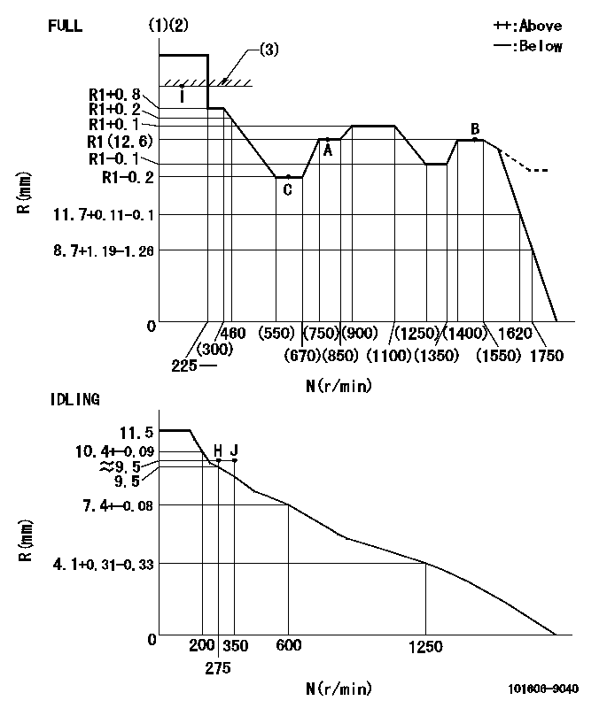
Test data Ex:
Governor adjustment

N:Pump speed
R:Rack position (mm)
(1)Torque cam stamping: T1
(2)Tolerance for racks not indicated: +-0.05mm.
(3)RACK LIMIT
----------
T1=H05
----------
----------
T1=H05
----------
Speed control lever angle

F:Full speed
I:Idle
(1)Use the hole at R = aa
(2)Stopper bolt set position 'H'
----------
aa=33mm
----------
a=26.5deg+-5deg b=38deg+-3deg
----------
aa=33mm
----------
a=26.5deg+-5deg b=38deg+-3deg
Stop lever angle

N:Pump normal
S:Stop the pump.
----------
----------
a=20deg+-5deg b=40deg+-5deg
----------
----------
a=20deg+-5deg b=40deg+-5deg
Timing setting

(1)Pump vertical direction
(2)Position of timer's threaded hole at No 1 cylinder's beginning of injection
(3)-
(4)-
----------
----------
a=(60deg)
----------
----------
a=(60deg)
Information:
1. Disconnect plug P7 from receptacle J7. The locking ring helps identify P7 from J7. Check the connections for damaged wires or pins and corrosion. Also check that the pins are at the proper height in the connector. Check that the wires and pins are tight in the connectors by pulling (slightly) on each wire of each connector (including the breakout "T").2. Install the 8T8695 Adapter (nine pin breakout "T") between J7 and P7. Twist the locking rings to secure the connections.3. Connect the voltmeter as shown. Check for the appropriate voltages between the lettered "T" pins as explained in Steps 4 through 11.4. Pin B (parking brake) to A (ground):* Less than .5 volts DC with the key on and parking brake applied.* More than 4.5 volts DC with the key on and parking brake released. Diagnosis - Disconnect breakout "T" and check the individual switch circuits for open, ground or faulty switch. Switch circuit must have less than 2.5 ohms resistance and more than 5000 ohms resistance to chassis ground.5. Pin C (brake switch) to A:* Less than .5 volts DC with the key on.* More than 4.5 volts DC with brake pedal applied and the key on. Diagnosis - Disconnect breakout "T" and check the individual switch circuits for open, ground or faulty switch. Switch circuit must have less than 2.5 ohms resistance and more than 5000 ohms resistance to chassis ground.
Vehicle Speed Buffer (1) Magnetic Pickup (2) in transmission. Step 6 checks the proper functioning of the truck wiring, vehicle speed sensor and vehicle speed buffer. If proper vehicle speed is present on the appropriate status screens of the 3176 (7X1055) DDT or the (8T8697) ECAP service tools during road test than Step 6 is not necessary.6. Pin D to pin A (static check): Disconnect the magnetic pickup (in transmission) from the input wires of the vehicle speed buffer.* Voltage should be 4.5 to 7.5 volts DC with the key on.
Vehicle Speed Buffer with Jumper Wire* With the jumper wire installed to the speed buffer input wires as shown, voltage is less than .75 volts DC with the key on. Diagnosis - If the voltages in both parts of Step 6 are correct, check the vehicle speed sensor per the manufactures specifications.In both parts of Step 6, if the voltage is 4.5 to 7.5 volts DC and does not change when the input wires are opened or jumpered: Remove breakout "T" and check wire from J7 pin D to J14 pin D for ground or open.* Remove the jumper wire and reconnect the magnetic pickup to vehicle speed buffer.7. Pin E to pin A:* Less than 1.0 volt DC with key on and foot pedal in low idle position.* More than 3.5 volts DC with foot pedal in high idle position. Diagnosis - Disconnect breakout "T". With the truck schematic, check wire E for continuity from J7 pin E to J11 pin C. Also check that wire E is not grounded to the
