Information injection-pump assembly
BOSCH
9 400 615 551
9400615551
ZEXEL
101606-9021
1016069021

Rating:
Service parts 101606-9021 INJECTION-PUMP ASSEMBLY:
1.
_
6.
COUPLING PLATE
7.
COUPLING PLATE
8.
_
9.
_
11.
Nozzle and Holder
12.
Open Pre:MPa(Kqf/cm2)
21.6{220}
15.
NOZZLE SET
Cross reference number
BOSCH
9 400 615 551
9400615551
ZEXEL
101606-9021
1016069021
Zexel num
Bosch num
Firm num
Name
101606-9021
9 400 615 551
HYUNDAI
INJECTION-PUMP ASSEMBLY
6D16 * K
6D16 * K
Calibration Data:
Adjustment conditions
Test oil
1404 Test oil ISO4113 or {SAEJ967d}
1404 Test oil ISO4113 or {SAEJ967d}
Test oil temperature
degC
40
40
45
Nozzle and nozzle holder
105780-8140
Bosch type code
EF8511/9A
Nozzle
105780-0000
Bosch type code
DN12SD12T
Nozzle holder
105780-2080
Bosch type code
EF8511/9
Opening pressure
MPa
17.2
Opening pressure
kgf/cm2
175
Injection pipe
Outer diameter - inner diameter - length (mm) mm 6-2-600
Outer diameter - inner diameter - length (mm) mm 6-2-600
Overflow valve
131424-5520
Overflow valve opening pressure
kPa
255
221
289
Overflow valve opening pressure
kgf/cm2
2.6
2.25
2.95
Tester oil delivery pressure
kPa
157
157
157
Tester oil delivery pressure
kgf/cm2
1.6
1.6
1.6
Direction of rotation (viewed from drive side)
Left L
Left L
Injection timing adjustment
Direction of rotation (viewed from drive side)
Left L
Left L
Injection order
1-5-3-6-
2-4
Pre-stroke
mm
3.3
3.25
3.35
Beginning of injection position
Governor side NO.1
Governor side NO.1
Difference between angles 1
Cal 1-5 deg. 60 59.5 60.5
Cal 1-5 deg. 60 59.5 60.5
Difference between angles 2
Cal 1-3 deg. 120 119.5 120.5
Cal 1-3 deg. 120 119.5 120.5
Difference between angles 3
Cal 1-6 deg. 180 179.5 180.5
Cal 1-6 deg. 180 179.5 180.5
Difference between angles 4
Cyl.1-2 deg. 240 239.5 240.5
Cyl.1-2 deg. 240 239.5 240.5
Difference between angles 5
Cal 1-4 deg. 300 299.5 300.5
Cal 1-4 deg. 300 299.5 300.5
Injection quantity adjustment
Adjusting point
B
Rack position
10.1
Pump speed
r/min
750
750
750
Average injection quantity
mm3/st.
51.7
50.7
52.7
Max. variation between cylinders
%
0
-2.5
2.5
Basic
*
Fixing the lever
*
Injection quantity adjustment_02
Adjusting point
C
Rack position
8.8+-0.5
Pump speed
r/min
285
285
285
Average injection quantity
mm3/st.
10
8.5
11.5
Max. variation between cylinders
%
0
-15
15
Fixing the rack
*
Injection quantity adjustment_03
Adjusting point
D
Rack position
-
Pump speed
r/min
100
100
100
Average injection quantity
mm3/st.
71
61
81
Fixing the lever
*
Rack limit
*
Timer adjustment
Pump speed
r/min
1200++
Advance angle
deg.
0
0
0
Remarks
Do not advance until starting N = 1200.
Do not advance until starting N = 1200.
Timer adjustment_02
Pump speed
r/min
-
Advance angle
deg.
1.5
1.5
1.5
Remarks
Measure the actual speed, stop
Measure the actual speed, stop
Test data Ex:
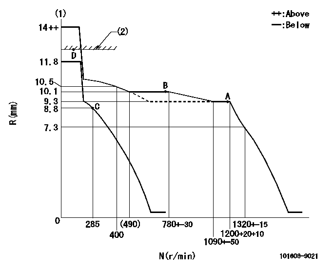
Governor adjustment

N:Pump speed
R:Rack position (mm)
(1)Target notch: K
(2)RACK LIMIT
----------
K=16
----------
----------
K=16
----------
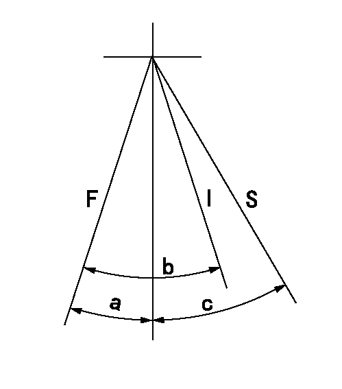
Speed control lever angle

F:Full speed
I:Idle
S:Stop
----------
----------
a=19deg+-5deg b=19deg+-5deg c=35deg+-3deg
----------
----------
a=19deg+-5deg b=19deg+-5deg c=35deg+-3deg
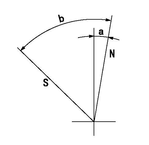
Stop lever angle

N:Pump normal
S:Stop the pump.
----------
----------
a=2.5deg+-5deg b=53deg+-5deg
----------
----------
a=2.5deg+-5deg b=53deg+-5deg
Timing setting

(1)Pump vertical direction
(2)Position of timer's tooth at No 1 cylinder's beginning of injection
(3)B.T.D.C.: aa
(4)-
----------
aa=18deg
----------
a=(2deg)
----------
aa=18deg
----------
a=(2deg)
Information:
White Smoke
Too Much White Or Blue Exhaust Smoke 1. Cold Outside TemperatureWhite smoke is normal in cold temperatures until the engine warms up. There will be less white smoke if No. 1 diesel or blended fuel is used.2. Engine Running Too ColdCheck the water temperature gauge in the cab. If the temperature remains below the minimum value of the gauge after a reasonable warm up time, this could indicate an open thermostat. Remove and test the thermostat. See the topic, Testing The Cooling System, in 3176 Diesel Truck Engine Systems Operation And Testing and Adjusting, Form No. SENR3909.3. Air In Fuel SystemDisconnect the fuel return line at the tank. Place this end of the line in a container of fuel to see if air bubbles are present when the engine is running. If air bubbles are observed, check for loose fittings or line leaks between the fuel tank and fuel transfer pump. If leaks are found, tighten the connections or replace the lines.To remove air from the engine fuel system: With the engine off, loosen the fuel return line fitting at the fuel manifold. Operate the fuel priming pump until the flow of fuel is free of air. Tighten the return line fitting, fasten the priming pump, and start the engine. If the engine still does not run smooth or produces a lot of white smoke, apply 35 kPa (5 psi) of air pressure to the fuel tank to force fuel through the system.
Do not use more than 55 kPa (8 psi) of air pressure in the fuel tank or damage to the tank may result.
Check the fuel return line for restriction. Replace if plugged.5. Fuel Injection Timing Out Of CalibrationCheck the fuel injection timing calibration and make necessary adjustments. See the topics, Engine Test Procedure Number P-402, [Checking Electronic Injection Timing With The Timing Adapter Tool Group And The ECAP (Electronic Control Analyzer and Programmer)], and Engine Test Procedure Number P-403, [Calibrating Electronic Injection Timing With The Timing Adapter Tool Group And The ECAP (Electronic Control Analyzer and Programmer)], in Electronic Troubleshooting, 3176 Diesel Truck Engine, Form No. SENR3913.6. Valve Adjustment Not CorrectCheck and make any necessary adjustments. See the topic, Valve Clearance Setting, in 3176 Diesel Truck Engine Systems Operation And Testing and Adjusting, Form No. SENR3909. Intake valve clearance is 0.38 mm (.015 in), and exhaust valve clearance is 0.64 mm (.025 in).7. Defective Unit InjectorsA defective unit injector can be found, by running the engine at the rpm where the problem exists, with the use of the Electronic Control Analyzer and Programmer (ECAP) service tool Interactive Diagnostics feature (single cylinder cutout, see Electronic Troubleshooting, 3176 Diesel Truck Engine, Form No. SENR3913) to stop the fuel supply to each cylinder in turn. If a cylinder is found where the cutout makes no difference on the engine performance, that injector should be removed and tested. Drain the fuel supply manifold and remove the injector(s) (see 3176 Diesel Truck Engine Disassembly and Assembly, Form No. SENR3914).Testing of
Have questions with 101606-9021?
Group cross 101606-9021 ZEXEL
Hyundai
101606-9021
9 400 615 551
INJECTION-PUMP ASSEMBLY
6D16
6D16
