Information injection-pump assembly
ZEXEL
101606-6992
1016066992
Rating:
Service parts 101606-6992 INJECTION-PUMP ASSEMBLY:
1.
_
6.
COUPLING PLATE
7.
COUPLING PLATE
8.
_
9.
_
11.
Nozzle and Holder
ME076615
12.
Open Pre:MPa(Kqf/cm2)
15.7{160}/21.6{220}
15.
NOZZLE SET
Cross reference number
ZEXEL
101606-6992
1016066992
Zexel num
Bosch num
Firm num
Name
101606-6992
INJECTION-PUMP ASSEMBLY
Calibration Data:
Adjustment conditions
Test oil
1404 Test oil ISO4113 or {SAEJ967d}
1404 Test oil ISO4113 or {SAEJ967d}
Test oil temperature
degC
40
40
45
Nozzle and nozzle holder
105780-8140
Bosch type code
EF8511/9A
Nozzle
105780-0000
Bosch type code
DN12SD12T
Nozzle holder
105780-2080
Bosch type code
EF8511/9
Opening pressure
MPa
17.2
Opening pressure
kgf/cm2
175
Injection pipe
Outer diameter - inner diameter - length (mm) mm 6-2-600
Outer diameter - inner diameter - length (mm) mm 6-2-600
Overflow valve
131424-5520
Overflow valve opening pressure
kPa
255
221
289
Overflow valve opening pressure
kgf/cm2
2.6
2.25
2.95
Tester oil delivery pressure
kPa
157
157
157
Tester oil delivery pressure
kgf/cm2
1.6
1.6
1.6
Direction of rotation (viewed from drive side)
Left L
Left L
Injection timing adjustment
Direction of rotation (viewed from drive side)
Left L
Left L
Injection order
1-5-3-6-
2-4
Pre-stroke
mm
3.2
3.15
3.25
Beginning of injection position
Governor side NO.1
Governor side NO.1
Difference between angles 1
Cal 1-5 deg. 60 59.5 60.5
Cal 1-5 deg. 60 59.5 60.5
Difference between angles 2
Cal 1-3 deg. 120 119.5 120.5
Cal 1-3 deg. 120 119.5 120.5
Difference between angles 3
Cal 1-6 deg. 180 179.5 180.5
Cal 1-6 deg. 180 179.5 180.5
Difference between angles 4
Cyl.1-2 deg. 240 239.5 240.5
Cyl.1-2 deg. 240 239.5 240.5
Difference between angles 5
Cal 1-4 deg. 300 299.5 300.5
Cal 1-4 deg. 300 299.5 300.5
Injection quantity adjustment
Adjusting point
-
Rack position
11.6
Pump speed
r/min
850
850
850
Each cylinder's injection qty
mm3/st.
72.5
70.3
74.7
Basic
*
Fixing the rack
*
Standard for adjustment of the maximum variation between cylinders
*
Injection quantity adjustment_02
Adjusting point
H
Rack position
9.5+-0.5
Pump speed
r/min
275
275
275
Each cylinder's injection qty
mm3/st.
8.3
7.1
9.5
Fixing the rack
*
Standard for adjustment of the maximum variation between cylinders
*
Injection quantity adjustment_03
Adjusting point
A
Rack position
R1(11.6)
Pump speed
r/min
850
850
850
Average injection quantity
mm3/st.
72.5
71.5
73.5
Basic
*
Fixing the lever
*
Injection quantity adjustment_04
Adjusting point
B
Rack position
R1-0.15
Pump speed
r/min
1400
1400
1400
Average injection quantity
mm3/st.
79.5
75.5
83.5
Fixing the lever
*
Injection quantity adjustment_05
Adjusting point
C
Rack position
R1+0.65
Pump speed
r/min
500
500
500
Average injection quantity
mm3/st.
71.5
67.5
75.5
Fixing the lever
*
Injection quantity adjustment_06
Adjusting point
I
Rack position
14.8+-0.
2
Pump speed
r/min
100
100
100
Average injection quantity
mm3/st.
120
100
140
Fixing the lever
*
Rack limit
*
Timer adjustment
Pump speed
r/min
1150
Advance angle
deg.
0.5
Timer adjustment_02
Pump speed
r/min
1200
Advance angle
deg.
0.9
0.4
1.4
Timer adjustment_03
Pump speed
r/min
1380
Advance angle
deg.
5
4.5
5.5
Remarks
Finish
Finish
Test data Ex:
Governor adjustment
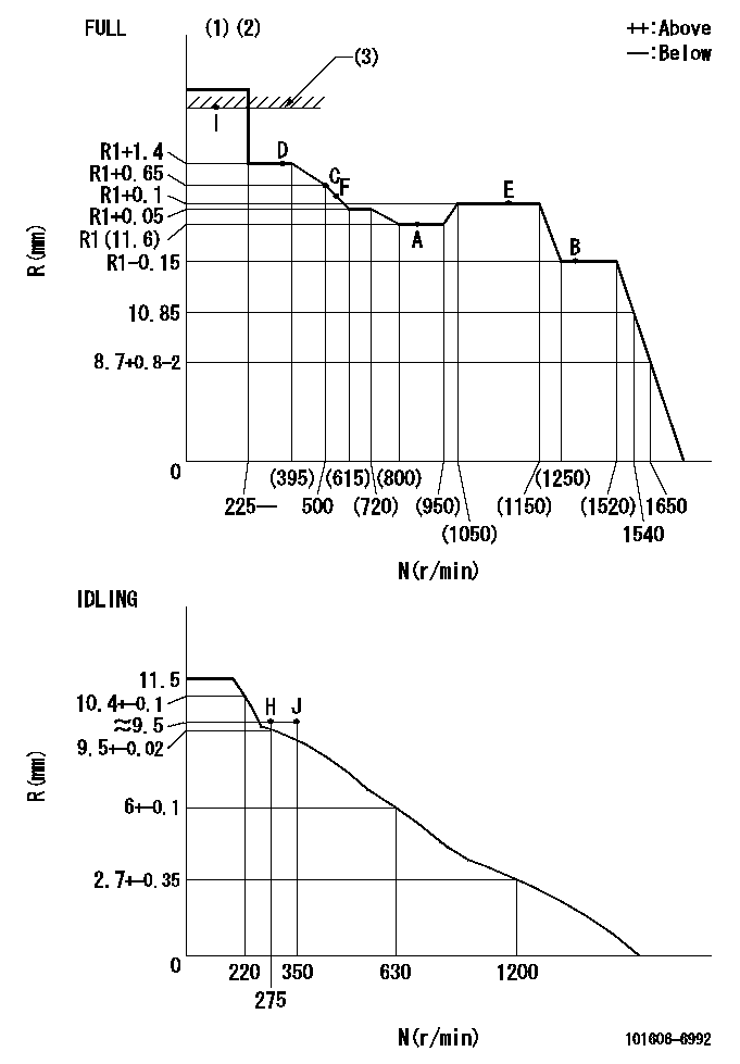
N:Pump speed
R:Rack position (mm)
(1)Torque cam stamping: T1
(2)Tolerance for racks not indicated: +-0.05mm.
(3)RACK LIMIT: RAL
----------
T1=F14 RAL=14.8+-0.2mm
----------
----------
T1=F14 RAL=14.8+-0.2mm
----------
Speed control lever angle
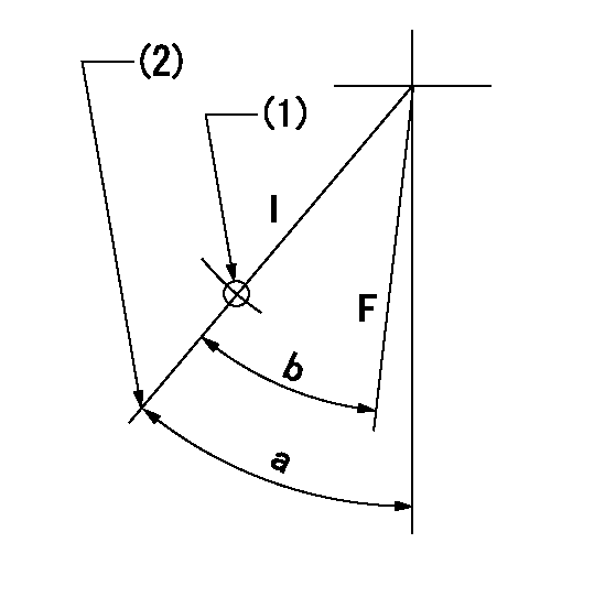
F:Full speed
I:Idle
(1)Use the hole at R = aa
(2)Stopper bolt set position 'H'
----------
aa=35mm
----------
a=41deg+-5deg b=(40deg)+-3deg
----------
aa=35mm
----------
a=41deg+-5deg b=(40deg)+-3deg
Stop lever angle
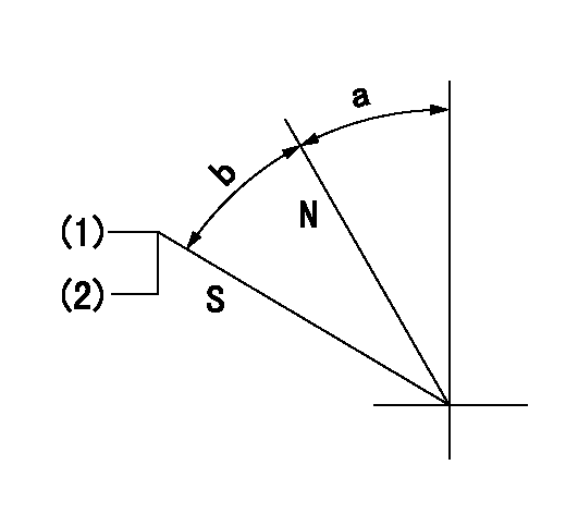
N:Pump normal
S:Stop the pump.
(1)Pump speed = aa and rack position = bb (non-injection rack position)
(2)Set the stopper bolt (confirm non-injection).
----------
aa=1400r/min bb=6.9-0.5mm
----------
a=32.5deg+-5deg b=25deg+-5deg
----------
aa=1400r/min bb=6.9-0.5mm
----------
a=32.5deg+-5deg b=25deg+-5deg
0000001501 MICRO SWITCH
Adjustment of the micro-switch
Adjust the bolt to obtain the following lever position when the micro-switch is ON.
(1)Speed N1
(2)Rack position Ra
----------
N1=400r/min Ra=9.2+-0.1mm
----------
----------
N1=400r/min Ra=9.2+-0.1mm
----------
Timing setting

(1)Pump vertical direction
(2)Position of timer's tooth at No 1 cylinder's beginning of injection
(3)B.T.D.C.: aa
(4)-
----------
aa=11deg
----------
a=(0deg)
----------
aa=11deg
----------
a=(0deg)
Information:
Overcooling
25. Defective Temperature GaugeIf the temperature gauge shows that the coolant temperature is below normal and all other conditions indicate that conditions are normal, check the coolant temperature in another method, such as:* Read the coolant temperature with an ECAP or DDT.* Install an 8T0470 Thermistor Thermometer Group* Install a temperature sensitive tape.* Install a new gauge that is known to be good.26. Defective Coolant Temperature SensorIf a fault is detected in the coolant temperature sensor circuit, determine if the fault is in the wiring or the coolant temperature sensor following the procedure in Electronic Troubleshooting, 3176 Diesel Truck Engine, Form No. SENR3913. Repair or replace parts as needed. The coolant temperature sensor should be accurate within plus or minus 3° C (6° F). Check the accuracy of the sensor if it is found to be out of specification.27. Long Idle PeriodsRunning the engine for extended periods of time under no load conditions will cause the engine heat to be removed at a faster rate than it is being generated.28. Very Light LoadsVery light loads, very slow speeds, or downhill travel can cause below normal heating due to the decreased amount of fuel that is being burned. The installation of shutters will help correct this problem by decreasing the flow of air into the engine compartment.29. Defective Water Temperature RegulatorIf the water temperature regulator is stuck open, it will cause below normal engine heating. To test the thermostat, see the topic, Testing The Cooling System, in the Testing and Adjusting section of Systems Operation, Testing and Adjusting, Form No. SENR3909.30. Faulty Fan Clutch (Will Not Disengage)Check for proper operation of the fan clutch. Refer to the Truck Manufacturer's Service Manual for the proper procedure.31. Vent Line OpenIf the vent line (OEM) between the temperature regulator and the radiator top tank is open, overcooling could result. Install a valve assembly in the line that will allow air venting but restrict coolant flow with the engine running.
25. Defective Temperature GaugeIf the temperature gauge shows that the coolant temperature is below normal and all other conditions indicate that conditions are normal, check the coolant temperature in another method, such as:* Read the coolant temperature with an ECAP or DDT.* Install an 8T0470 Thermistor Thermometer Group* Install a temperature sensitive tape.* Install a new gauge that is known to be good.26. Defective Coolant Temperature SensorIf a fault is detected in the coolant temperature sensor circuit, determine if the fault is in the wiring or the coolant temperature sensor following the procedure in Electronic Troubleshooting, 3176 Diesel Truck Engine, Form No. SENR3913. Repair or replace parts as needed. The coolant temperature sensor should be accurate within plus or minus 3° C (6° F). Check the accuracy of the sensor if it is found to be out of specification.27. Long Idle PeriodsRunning the engine for extended periods of time under no load conditions will cause the engine heat to be removed at a faster rate than it is being generated.28. Very Light LoadsVery light loads, very slow speeds, or downhill travel can cause below normal heating due to the decreased amount of fuel that is being burned. The installation of shutters will help correct this problem by decreasing the flow of air into the engine compartment.29. Defective Water Temperature RegulatorIf the water temperature regulator is stuck open, it will cause below normal engine heating. To test the thermostat, see the topic, Testing The Cooling System, in the Testing and Adjusting section of Systems Operation, Testing and Adjusting, Form No. SENR3909.30. Faulty Fan Clutch (Will Not Disengage)Check for proper operation of the fan clutch. Refer to the Truck Manufacturer's Service Manual for the proper procedure.31. Vent Line OpenIf the vent line (OEM) between the temperature regulator and the radiator top tank is open, overcooling could result. Install a valve assembly in the line that will allow air venting but restrict coolant flow with the engine running.
Have questions with 101606-6992?
Group cross 101606-6992 ZEXEL
Mitsubishi
Mitsubishi
101606-6992
INJECTION-PUMP ASSEMBLY
