Information injection-pump assembly
BOSCH
9 400 615 546
9400615546
ZEXEL
101606-6970
1016066970
MITSUBISHI
ME076598
me076598

Rating:
Service parts 101606-6970 INJECTION-PUMP ASSEMBLY:
1.
_
6.
COUPLING PLATE
7.
COUPLING PLATE
8.
_
9.
_
11.
Nozzle and Holder
ME035655
12.
Open Pre:MPa(Kqf/cm2)
21.6{220}
15.
NOZZLE SET
Cross reference number
BOSCH
9 400 615 546
9400615546
ZEXEL
101606-6970
1016066970
MITSUBISHI
ME076598
me076598
Zexel num
Bosch num
Firm num
Name
101606-6970
9 400 615 546
ME076598 MITSUBISHI
INJECTION-PUMP ASSEMBLY
6D14 * K
6D14 * K
Calibration Data:
Adjustment conditions
Test oil
1404 Test oil ISO4113 or {SAEJ967d}
1404 Test oil ISO4113 or {SAEJ967d}
Test oil temperature
degC
40
40
45
Nozzle and nozzle holder
105780-8140
Bosch type code
EF8511/9A
Nozzle
105780-0000
Bosch type code
DN12SD12T
Nozzle holder
105780-2080
Bosch type code
EF8511/9
Opening pressure
MPa
17.2
Opening pressure
kgf/cm2
175
Injection pipe
Outer diameter - inner diameter - length (mm) mm 6-2-600
Outer diameter - inner diameter - length (mm) mm 6-2-600
Overflow valve
131424-5520
Overflow valve opening pressure
kPa
255
221
289
Overflow valve opening pressure
kgf/cm2
2.6
2.25
2.95
Tester oil delivery pressure
kPa
157
157
157
Tester oil delivery pressure
kgf/cm2
1.6
1.6
1.6
Direction of rotation (viewed from drive side)
Left L
Left L
Injection timing adjustment
Direction of rotation (viewed from drive side)
Left L
Left L
Injection order
1-5-3-6-
2-4
Pre-stroke
mm
3.3
3.25
3.35
Beginning of injection position
Governor side NO.1
Governor side NO.1
Difference between angles 1
Cal 1-5 deg. 60 59.5 60.5
Cal 1-5 deg. 60 59.5 60.5
Difference between angles 2
Cal 1-3 deg. 120 119.5 120.5
Cal 1-3 deg. 120 119.5 120.5
Difference between angles 3
Cal 1-6 deg. 180 179.5 180.5
Cal 1-6 deg. 180 179.5 180.5
Difference between angles 4
Cyl.1-2 deg. 240 239.5 240.5
Cyl.1-2 deg. 240 239.5 240.5
Difference between angles 5
Cal 1-4 deg. 300 299.5 300.5
Cal 1-4 deg. 300 299.5 300.5
Injection quantity adjustment
Adjusting point
-
Rack position
11
Pump speed
r/min
850
850
850
Each cylinder's injection qty
mm3/st.
65
63
67
Basic
*
Fixing the rack
*
Standard for adjustment of the maximum variation between cylinders
*
Injection quantity adjustment_02
Adjusting point
H
Rack position
9.5+-0.5
Pump speed
r/min
275
275
275
Each cylinder's injection qty
mm3/st.
10.5
9
12
Fixing the rack
*
Standard for adjustment of the maximum variation between cylinders
*
Injection quantity adjustment_03
Adjusting point
A
Rack position
R1(11)
Pump speed
r/min
850
850
850
Average injection quantity
mm3/st.
65
64
66
Basic
*
Fixing the lever
*
Injection quantity adjustment_04
Adjusting point
B
Rack position
R1(11)
Pump speed
r/min
1450
1450
1450
Average injection quantity
mm3/st.
77.5
75.5
79.5
Fixing the lever
*
Injection quantity adjustment_05
Adjusting point
C
Rack position
R1+0.4
Pump speed
r/min
600
600
600
Average injection quantity
mm3/st.
59.7
55.7
63.7
Fixing the lever
*
Injection quantity adjustment_06
Adjusting point
I
Rack position
14.1+-0.
5
Pump speed
r/min
100
100
100
Average injection quantity
mm3/st.
90
70
110
Fixing the lever
*
Rack limit
*
Timer adjustment
Pump speed
r/min
900--
Advance angle
deg.
0
0
0
Remarks
Start
Start
Timer adjustment_02
Pump speed
r/min
850
Advance angle
deg.
0.5
Timer adjustment_03
Pump speed
r/min
900
Advance angle
deg.
0.8
Timer adjustment_04
Pump speed
r/min
1200
Advance angle
deg.
2.6
2.1
3.1
Timer adjustment_05
Pump speed
r/min
1500
Advance angle
deg.
5.5
5
6
Remarks
Finish
Finish
Test data Ex:
Governor adjustment
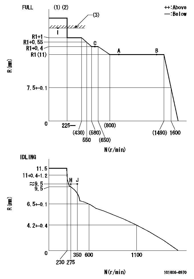
N:Pump speed
R:Rack position (mm)
(1)Torque cam stamping: T1
(2)Tolerance for racks not indicated: +-0.05mm.
(3)RACK LIMIT
----------
T1=D52
----------
----------
T1=D52
----------
Speed control lever angle
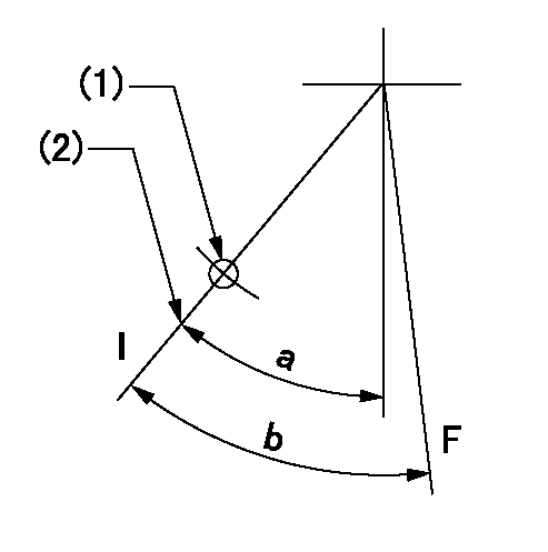
F:Full speed
I:Idle
(1)Use the hole at R = aa
(2)Stopper bolt set position 'H'
----------
aa=35mm
----------
a=33deg+-5deg b=40.5deg+-3deg
----------
aa=35mm
----------
a=33deg+-5deg b=40.5deg+-3deg
Stop lever angle

N:Engine manufacturer's normal use
S:Stop the pump.
(1)Set the stopper bolt at pump speed = aa and rack position = bb (non-injection rack position). Confirm non-injection.
(2)After setting the stopper bolt, confirm non-injection at speed cc. Rack position = dd (non-injection rack position).
(3)Rack position = approximately ee.
(4)Free (at shipping)
----------
aa=1550r/min bb=5.4-0.5mm cc=275r/min dd=(7.4)mm ee=17.4mm
----------
a=17deg+-5deg b=2deg+-5deg c=(27deg)
----------
aa=1550r/min bb=5.4-0.5mm cc=275r/min dd=(7.4)mm ee=17.4mm
----------
a=17deg+-5deg b=2deg+-5deg c=(27deg)
0000001501 MICRO SWITCH
Adjustment of the micro-switch
Adjust the bolt to obtain the following lever position when the micro-switch is ON.
(1)Speed N1
(2)Rack position Ra
----------
N1=400r/min Ra=9.2+-0.1mm
----------
----------
N1=400r/min Ra=9.2+-0.1mm
----------
0000001601 ACS
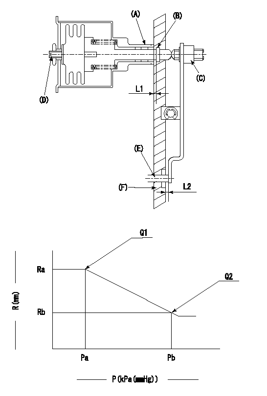
(A) Housing
(B) Snap ring
(C) adjusting screw
(D) Set screw
(E): Push rod
(F) Spacer
1. Adjustment of the aneroid compensator
(1)Adjust with the (D) set screw so that the clearance between the (A) housing and (B) snap ring is L1.
(2)Select the push rod (E) so that the distance from the end surface of the (F) spacer becomes L2.
(3)(C) Turn the screw to adjust the beginning of aneroid compensator operation.
2. Adjustment when mounting the governor.
(1)Set the speed of the pump to N1 r/min and fix the control lever at the full set position.
(2)Adjust using screw C to obtain the performance shown in the graph above.
(3)After final adjustment, confirm that the gap between housing (A) and snapring (B) is L3.
----------
N1=850r/min L1=1.4~1.7mm L2=0.5+-0.5mm L3=(0.1~0.5)mm
----------
Ra=R1(11)mm Rb=R1-0.3mm Pa=(89.8)kPa((674)mmHg) Pb=79.4+-0.7kPa(596+-5mmHg) Q1=65+-1cm3/1000st Q2=(59)cm3/1000st
----------
N1=850r/min L1=1.4~1.7mm L2=0.5+-0.5mm L3=(0.1~0.5)mm
----------
Ra=R1(11)mm Rb=R1-0.3mm Pa=(89.8)kPa((674)mmHg) Pb=79.4+-0.7kPa(596+-5mmHg) Q1=65+-1cm3/1000st Q2=(59)cm3/1000st
Timing setting

(1)Pump vertical direction
(2)Position of timer's tooth at No 1 cylinder's beginning of injection
(3)B.T.D.C.: aa
(4)-
----------
aa=16deg
----------
a=(1deg)
----------
aa=16deg
----------
a=(1deg)
Information:
2. Turn the crankshaft until two pistons are at bottom center.3. Remove nuts (1) and the bearing caps. Push the rods and pistons up until the rings are out of the cylinder liners. 4. Remove pistons (2) and connecting rods from the cylinder liners.5. Do Steps 1 through 4 for the remainder of the pistons and connecting rods.Install Pistons And Connecting Rod Assemblies
1. Put clean engine oil on piston rings, connecting rod bearings and cylinder liners. 2. Use tool (A), and install piston (2) and the connecting rod in the cylinder liner. Be sure the number on the tab groove side of the connecting rod is on the opposite side from the camshaft.3. Install the bearing cap on the connecting rod with the number on the side of the bearing cap on the same side and same number as on the connecting rod.4a. For connecting rods with bolts and nuts, use the following torque procedure: Apply clean engine oil to the bolt threads, nuts, and seating faces of the bearing cap. Tighten each nut to a torque of 80 5 N m (60 4 lb.ft.). Tighten each nut an additional 120° 5°.4b. For connecting rods with only bolts, use the following torque procedure: Apply Molylube to the threads of the bolts and to the seating faces of the bearing cap and the bolt. Tighten each bolt to a torque of 90 8 N m (66 6 lb.ft.). Tighten each bolt an additional 90° 5°.5. Do Steps 1 through 4 for the remainder of the pistons and connecting rods.End By:a. install oil pumpb. install cylinder head assembly.Disassemble And Assemble Pistons And Connecting Rod Assemblies
Start By:a. remove pistons and connecting rod assemblies 1. Remove bearings (3) from the connecting rod and connecting rod cap.2. Remove retainer ring (1) and tool (A).3. Remove pin (2) and connecting rod (4) from the piston. 4. Remove piston rings (5) from the piston with tool (B). Clean the piston ring grooves on the pistons with an acceptable ring groove cleaning tool. See, Use Of Piston Pin Bearing Removal And Installation Tools, Special Instructions, Form No. SMHS7295.5. Heat connecting rod (4) in an oven to a temperature of 177° to 260° C (350° to 500° F). Never use a direct flame to heat a connecting rod. 6. Put connecting rod (4) in position on the base plate of tooling (C). Put a new rod pin bearing (6) on the adapter part of tooling (C). The old bearing is pushed out by tooling (C) as the new bearing is installed.7. Use tooling (C) to push the new bearing into the connecting rod until the push adapter of tooling (C) makes full contact with the connecting rod surface.8. Use a pin boring machine to make the rod pin bearing the correct size. The bore in the new rod pin bearing must be 50.830 0.008 mm (2.0012 .0003 in.).9. Check the clearance between the ends of the piston rings. See
Have questions with 101606-6970?
Group cross 101606-6970 ZEXEL
Mitsubishi
101606-6970
9 400 615 546
ME076598
INJECTION-PUMP ASSEMBLY
6D14
6D14