Information injection-pump assembly
BOSCH
F 01G 09U 04N
f01g09u04n
ZEXEL
101606-6791
1016066791
MITSUBISHI
ME076551
me076551
Rating:
Include in #1:
101402-4932
as _
Cross reference number
BOSCH
F 01G 09U 04N
f01g09u04n
ZEXEL
101606-6791
1016066791
MITSUBISHI
ME076551
me076551
Zexel num
Bosch num
Firm num
Name
Calibration Data:
Adjustment conditions
Test oil
1404 Test oil ISO4113 or {SAEJ967d}
1404 Test oil ISO4113 or {SAEJ967d}
Test oil temperature
degC
40
40
45
Nozzle and nozzle holder
105780-8140
Bosch type code
EF8511/9A
Nozzle
105780-0000
Bosch type code
DN12SD12T
Nozzle holder
105780-2080
Bosch type code
EF8511/9
Opening pressure
MPa
17.2
Opening pressure
kgf/cm2
175
Injection pipe
Outer diameter - inner diameter - length (mm) mm 6-2-600
Outer diameter - inner diameter - length (mm) mm 6-2-600
Overflow valve
131424-5520
Overflow valve opening pressure
kPa
255
221
289
Overflow valve opening pressure
kgf/cm2
2.6
2.25
2.95
Tester oil delivery pressure
kPa
157
157
157
Tester oil delivery pressure
kgf/cm2
1.6
1.6
1.6
Direction of rotation (viewed from drive side)
Left L
Left L
Injection timing adjustment
Direction of rotation (viewed from drive side)
Left L
Left L
Injection order
1-5-3-6-
2-4
Pre-stroke
mm
4.2
4.15
4.25
Beginning of injection position
Governor side NO.1
Governor side NO.1
Difference between angles 1
Cal 1-5 deg. 60 59.5 60.5
Cal 1-5 deg. 60 59.5 60.5
Difference between angles 2
Cal 1-3 deg. 120 119.5 120.5
Cal 1-3 deg. 120 119.5 120.5
Difference between angles 3
Cal 1-6 deg. 180 179.5 180.5
Cal 1-6 deg. 180 179.5 180.5
Difference between angles 4
Cyl.1-2 deg. 240 239.5 240.5
Cyl.1-2 deg. 240 239.5 240.5
Difference between angles 5
Cal 1-4 deg. 300 299.5 300.5
Cal 1-4 deg. 300 299.5 300.5
Injection quantity adjustment
Adjusting point
-
Rack position
11.3
Pump speed
r/min
850
850
850
Each cylinder's injection qty
mm3/st.
74.5
72.3
76.7
Basic
*
Fixing the rack
*
Standard for adjustment of the maximum variation between cylinders
*
Injection quantity adjustment_02
Adjusting point
H
Rack position
9.5+-0.5
Pump speed
r/min
275
275
275
Each cylinder's injection qty
mm3/st.
8
6.8
9.2
Fixing the rack
*
Standard for adjustment of the maximum variation between cylinders
*
Injection quantity adjustment_03
Adjusting point
A
Rack position
R1(11.3)
Pump speed
r/min
850
850
850
Average injection quantity
mm3/st.
74.5
73.5
75.5
Basic
*
Fixing the lever
*
Injection quantity adjustment_04
Adjusting point
B
Rack position
R1-0.1
Pump speed
r/min
1400
1400
1400
Average injection quantity
mm3/st.
83.5
79.5
87.5
Fixing the lever
*
Injection quantity adjustment_05
Adjusting point
C
Rack position
R1+0.4
Pump speed
r/min
500
500
500
Average injection quantity
mm3/st.
69
65
73
Fixing the lever
*
Injection quantity adjustment_06
Adjusting point
I
Rack position
-
Pump speed
r/min
100
100
100
Average injection quantity
mm3/st.
146
136
156
Fixing the lever
*
Rack limit
*
Timer adjustment
Pump speed
r/min
1150
Advance angle
deg.
0.5
Timer adjustment_02
Pump speed
r/min
1200
Advance angle
deg.
0.9
0.4
1.4
Timer adjustment_03
Pump speed
r/min
1380
Advance angle
deg.
5
4.5
5.5
Remarks
Finish
Finish
Test data Ex:
Governor adjustment
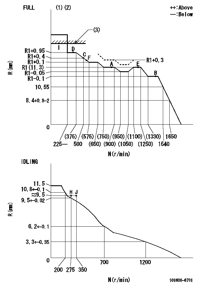
N:Pump speed
R:Rack position (mm)
(1)Torque cam stamping: T1
(2)Tolerance for racks not indicated: +-0.05mm.
(3)RACK LIMIT
----------
T1=E45
----------
----------
T1=E45
----------
Speed control lever angle

F:Full speed
I:Idle
(1)Stopper bolt set position 'H'
----------
----------
a=18.5deg+-5deg b=40deg+-3deg
----------
----------
a=18.5deg+-5deg b=40deg+-3deg
Stop lever angle
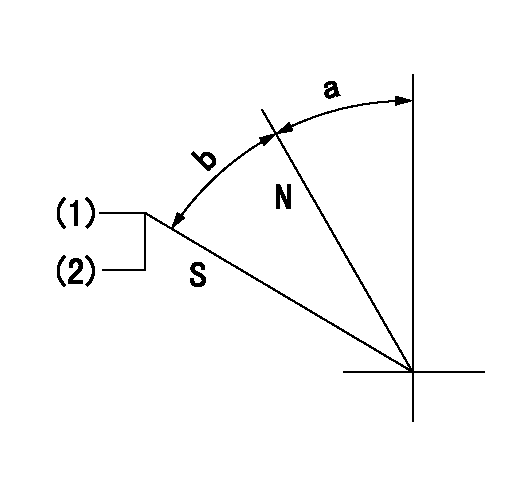
N:Pump normal
S:Stop the pump.
(1)Set the stopper bolt at pump speed = aa and rack position = bb (non-injection rack position). Confirm non-injection.
(2)After setting the stopper bolt, confirm non-injection at speed cc. Rack position = dd (non-injection rack position).
----------
aa=1400r/min bb=6.5-0.5mm cc=275r/min dd=(8.5)-0.5mm
----------
a=11.5deg+-5deg b=27deg+-5deg
----------
aa=1400r/min bb=6.5-0.5mm cc=275r/min dd=(8.5)-0.5mm
----------
a=11.5deg+-5deg b=27deg+-5deg
0000001501 MICRO SWITCH
Adjustment of the micro-switch
Adjust the bolt to obtain the following lever position when the micro-switch is ON.
(1)Speed N1
(2)Rack position Ra
----------
N1=400r/min Ra=9.2+-0.1mm
----------
----------
N1=400r/min Ra=9.2+-0.1mm
----------
0000001601 LEVER

(A) Accelerator lever stopper bolt
(B) Link
(c) Nut
(D) Lever
(E) Pin
(f) lever
(G) Stopper bolt
(H) Return spring
(J) Pin (E) contacts lever.
(K) Load sensor terminal
(1)Black
(2)Blue-yellow
(3)Blue-red
Setting the accelerator lever angle, load sensor adjustment
1. Accelerator lever setting method
(1)Position the speed lever against the idle stopper bolt and fix.
(2)Screw in the accelerator lever stopper bolt (A) and back off the stopper bolt (A) from the position where the accelerator lever pin contacts the speed lever and set. (Gap: approx. 1 mm)
Tightening torque: 4.9~7 N.m {0.5~0.7 kgf.m}
2. Load sensor adjustment (See fig 1)
(1)Load sensor output measuring circuit
Apply DC5+-0.01V to the load sensor terminals and measure the output voltage.
(2)Load sensor output adjustment procedure
Hold the speed lever against the full side stopper bolt and fix. Adjust the load sensor output voltage to VF = 0.417+-0.1 V using the link (B) and then fix temporarily using nut (C).
Turn the speed lever from the idle side to the full side and confirm that output voltage VF = 0.417+-0.1 V is obtained. Confirm several times and then fix using nut (C).
Tightening torque: 3.4~4.9 N.m {0.35~0.5 kgf.m}
3. Setting the step motor's idle side stopper bolt
After adjustment in previous 1 and 2, position speed lever against idle stopper bolt and fix. Then, screw in stopper bolt G until step motor lever D's pin E contacts lever F. Back off 10+2 deg (approx. 3.5 mm) from this position and fix G. (See fig. 3)
4. Speed lever return confirmation
(1)Remove return spring (H) and confirm that the speed lever is returned to the idle position by the torsion spring.
(2)Reinstall the return spring (H) in its original position.
----------
----------
----------
----------
0000001701 TAMPER PROOF
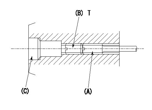
1. Method for setting tamperproof proofing
(1)Perform after governor adjustment (torque cam phase adjustment).
(2)Increase the full rack position to aa using the load lever.
(3)At N = N1, push in screw (A) until Ra.
(4)Temporarily caulk using the tip of a screwdriver
(5)Confirm that the rack at that time is Rb.
(6)Lock using setscrew (B). (Tightening torque = T)
(7)Pressfit (C) after applying adhesive.
(8)Readjust the full rack using the load lever.
----------
aa=(0.4)mm N1=850r/min Ra=(R1+0.3)mm Rb=(R1+0.3)mm
----------
T=3.4~4.9N-m(0.35~0.5Kgf-m)
----------
aa=(0.4)mm N1=850r/min Ra=(R1+0.3)mm Rb=(R1+0.3)mm
----------
T=3.4~4.9N-m(0.35~0.5Kgf-m)
Timing setting

(1)Pump vertical direction
(2)Position of timer's tooth at No 1 cylinder's beginning of injection
(3)B.T.D.C.: aa
(4)-
----------
aa=11deg
----------
a=(1deg)
----------
aa=11deg
----------
a=(1deg)
Information:
1. Remove nuts (2) and remove cover (1) from the timing gear cover. Remove the gasket from cover (1). 2. Remove bolts and washers (3). Remove cover (4). 3. Remove O-ring seals (5) from cover (4). 4. Remove bolts (6). Remove ring (7) and the gear. 5. Remove fuel injection lines (9). Put caps and plugs on the openings of the pump and lines to prevent contamination from entering the fuel system.6. Remove tube assembly (8). Remove tube assemblies (11) and fuel manifold (10). Remove fuel transfer pump (12). 7. The weight of the fuel injection pump housing and governor is 57 kg (125 lb.). Attach a hoist to the fuel injection pump housing, and remove two bolts (16), and two bolts (17).8. Remove two nuts (13) and bolt (14). Remove fuel injection pump housing and governor (15). 9. Remove O-ring seals (18) from fuel injection pump housing (15). The following steps are for the installation of the fuel injection pump housing and governor.10. Attach a hoist to the fuel injection pump housing and governor (15). Be sure that the three O-ring seals are in position on the fuel infection pump housing. Install the fuel injection pump housing and governor on the timing gear housing.11. Install fuel transfer pump (12) and fuel manifold (10). Install tube assemblies (8) and (11).12. Install fuel injection lines (9). 13. Put gear (19) in position in the front timing gear cover. 14. Install two 3/8"-16 NC × 152.4 mm (6 in.) guide bolts (20) in gear (19) as shown. 15. Install ring (7). Install two bolts (6) finger tight. Remove guide pins (20) and install the remaining bolts (6). Tighten bolts (6) to a torque of 3 N m (27 lb. in.).16. Put the O-ring seals on cover (4). Lubricate the seals with clean engine oil. Put cover (4) in postion on ring (7) and install bolts and washers (3). 17. Put the No. 1 piston at top center on the compression stroke. Make reference to the topic, Finding Top Center Compression Position For No. 1 Piston, in Testing And Adjusting. Remove the timing bolt from the flywheel, and use tool (A) to rotate the crankshaft clockwise (opposite the direction of engine rotation) 45°. 18. Remove the plug from the fuel injection pump housing. Install tool (B) in the fuel injection pump housing as shown. Slowly rotate the crankshaft counterclockwise (direction of engine rotation) until the timing pin goes into the slot in the fuel injection pump camshaft.
Too much pressure on the timing pin can damage the fuel injection pump or the timing pin.
19. Put the timing bolt in the timing hole in the flywheel housing. Rotate the crankshaft counterclockwise (as viewed from the flywheel end of the engine) until the fuel pump camshaft is tight against tool (B). This removes gear clearance from the drive train. If the bolt can be installed in the timing hole in the flywheel, the timing of the fuel injection pump is correct.20. If the