Information injection-pump assembly
BOSCH
9 400 615 529
9400615529
ZEXEL
101606-6640
1016066640
MITSUBISHI
ME076495
me076495

Rating:
Service parts 101606-6640 INJECTION-PUMP ASSEMBLY:
1.
_
6.
COUPLING PLATE
7.
COUPLING PLATE
8.
_
9.
_
11.
Nozzle and Holder
ME035655
12.
Open Pre:MPa(Kqf/cm2)
21.6{220}
15.
NOZZLE SET
Cross reference number
BOSCH
9 400 615 529
9400615529
ZEXEL
101606-6640
1016066640
MITSUBISHI
ME076495
me076495
Zexel num
Bosch num
Firm num
Name
101606-6640
9 400 615 529
ME076495 MITSUBISHI
INJECTION-PUMP ASSEMBLY
6D14 * K 14BE INJECTION PUMP ASSY PE6A PE
6D14 * K 14BE INJECTION PUMP ASSY PE6A PE
Calibration Data:
Adjustment conditions
Test oil
1404 Test oil ISO4113 or {SAEJ967d}
1404 Test oil ISO4113 or {SAEJ967d}
Test oil temperature
degC
40
40
45
Nozzle and nozzle holder
105780-8140
Bosch type code
EF8511/9A
Nozzle
105780-0000
Bosch type code
DN12SD12T
Nozzle holder
105780-2080
Bosch type code
EF8511/9
Opening pressure
MPa
17.2
Opening pressure
kgf/cm2
175
Injection pipe
Outer diameter - inner diameter - length (mm) mm 6-2-600
Outer diameter - inner diameter - length (mm) mm 6-2-600
Overflow valve
131424-5520
Overflow valve opening pressure
kPa
255
221
289
Overflow valve opening pressure
kgf/cm2
2.6
2.25
2.95
Tester oil delivery pressure
kPa
157
157
157
Tester oil delivery pressure
kgf/cm2
1.6
1.6
1.6
Direction of rotation (viewed from drive side)
Left L
Left L
Injection timing adjustment
Direction of rotation (viewed from drive side)
Left L
Left L
Injection order
1-5-3-6-
2-4
Pre-stroke
mm
3.3
3.25
3.35
Beginning of injection position
Governor side NO.1
Governor side NO.1
Difference between angles 1
Cal 1-5 deg. 60 59.5 60.5
Cal 1-5 deg. 60 59.5 60.5
Difference between angles 2
Cal 1-3 deg. 120 119.5 120.5
Cal 1-3 deg. 120 119.5 120.5
Difference between angles 3
Cal 1-6 deg. 180 179.5 180.5
Cal 1-6 deg. 180 179.5 180.5
Difference between angles 4
Cyl.1-2 deg. 240 239.5 240.5
Cyl.1-2 deg. 240 239.5 240.5
Difference between angles 5
Cal 1-4 deg. 300 299.5 300.5
Cal 1-4 deg. 300 299.5 300.5
Injection quantity adjustment
Adjusting point
-
Rack position
10.8
Pump speed
r/min
850
850
850
Each cylinder's injection qty
mm3/st.
65
63
67
Basic
*
Fixing the rack
*
Standard for adjustment of the maximum variation between cylinders
*
Injection quantity adjustment_02
Adjusting point
H
Rack position
9.5+-0.5
Pump speed
r/min
275
275
275
Each cylinder's injection qty
mm3/st.
10.5
9
12
Fixing the rack
*
Standard for adjustment of the maximum variation between cylinders
*
Injection quantity adjustment_03
Adjusting point
A
Rack position
R1(10.8)
Pump speed
r/min
850
850
850
Average injection quantity
mm3/st.
65
64
66
Basic
*
Fixing the lever
*
Injection quantity adjustment_04
Adjusting point
B
Rack position
R1(10.8)
Pump speed
r/min
1450
1450
1450
Average injection quantity
mm3/st.
77.5
75.5
79.5
Fixing the lever
*
Injection quantity adjustment_05
Adjusting point
C
Rack position
R1+0.4
Pump speed
r/min
600
600
600
Average injection quantity
mm3/st.
59.7
55.7
63.7
Fixing the lever
*
Injection quantity adjustment_06
Adjusting point
I
Rack position
14.1+-0.
5
Pump speed
r/min
100
100
100
Average injection quantity
mm3/st.
90
70
110
Fixing the lever
*
Rack limit
*
Timer adjustment
Pump speed
r/min
850
Advance angle
deg.
0.5
Timer adjustment_02
Pump speed
r/min
900
Advance angle
deg.
0.8
Timer adjustment_03
Pump speed
r/min
1200
Advance angle
deg.
2.6
2.1
3.1
Timer adjustment_04
Pump speed
r/min
1500
Advance angle
deg.
5.5
5
6
Remarks
Finish
Finish
Test data Ex:
Governor adjustment
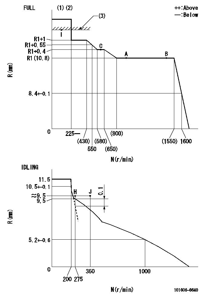
N:Pump speed
R:Rack position (mm)
(1)Torque cam stamping: T1
(2)Tolerance for racks not indicated: +-0.05mm.
(3)RACK LIMIT
----------
T1=D39
----------
----------
T1=D39
----------
Speed control lever angle

F:Full speed
I:Idle
(1)Stopper bolt set position 'H'
----------
----------
a=10deg+-5deg b=42deg+-3deg
----------
----------
a=10deg+-5deg b=42deg+-3deg
Stop lever angle

N:Engine manufacturer's normal use
S:Stop the pump.
(1)Set the stopper bolt at pump speed = aa and rack position = bb (non-injection rack position). Confirm non-injection.
(2)After setting the stopper bolt, confirm non-injection at speed cc. Rack position = dd (non-injection rack position).
(3)Rack position = approximately ee.
(4)Free (at shipping)
----------
aa=1550r/min bb=7.2-0.5mm cc=275r/min dd=8.2mm ee=17.4mm
----------
a=38.5deg+-5deg b=(27deg) c=17deg+-5deg
----------
aa=1550r/min bb=7.2-0.5mm cc=275r/min dd=8.2mm ee=17.4mm
----------
a=38.5deg+-5deg b=(27deg) c=17deg+-5deg
Timing setting

(1)Pump vertical direction
(2)Position of timer's tooth at No 1 cylinder's beginning of injection
(3)B.T.D.C.: aa
(4)-
----------
aa=16deg
----------
a=(1deg)
----------
aa=16deg
----------
a=(1deg)
Information:
Step 8. Check Signal Voltage At ECMA. Install the 40-Pin Breakout 'T' at the ECM Connector (J4/P4).B. Measure the voltage between Fuel Pressure, Pin 39 and Sensor Return Analog, Pin 35. The signal voltage should correspond to the observed fuel pressure reading shown in Table A. OK: The Fuel Pressure Signal is reaching the ECM. If Step 3 found that the ECM is not reading fuel pressure correctly, then the ECM is defective. Replace the ECM. Stop. NOT OK: The signal was good at the sensor but did not reach the ECM. Repair the wiring harness between Fuel Pressure Sensor and the ECM. Stop.P227: Retarder Enable Signal Test
The "Retarder Enable" signal is provided by the ECM to indicate that conditions are acceptable for an engine retarder to operate. Operation of the retarder is inhibited during undesirable engine operating conditions (such as while the engine is being fueled).With the Cruise Control ON/OFF Switch in the OFF position, the retarder is enabled under the following conditions:* engine rpm is greater than 950 rpm and* driver's foot is off the throttle pedal and the clutch pedalWith the Cruise Control ON/OFF Switch "ON", the operation of the retarder is also controlled through the customer parameter "Engine Retarder Mode". Programming the parameter to "COAST" allows retarding with the service brakes applied, but allows the engine to coast with no retarding after they are released. Programming the parameter to "LATCH" allows retarding with the service brake applied and keeps the retarder latched on after the service brakes are released (until engine rpm drops below 950 rpm or the driver presses the throttle or clutch pedal).The Retarder Enable Signal should be 15% Duty Cycle (nominal) to indicate that the retarder is enabled and 85% Duty Cycle (nominal) to indicate that it is disabled. The remainder of the engine retarder circuit is supplied by the OEM. In typical installations, the Retarder Enable signal isused by a separate Brake Control Module, which then energize the retarder solenoids. An "Engine Brake On" Switch is also typically connected to the Brake Control Module, and must be ON before the brake will operate. Step 1. Inspect Connectors And Wiring HarnessInspect the Vehicle Connector (J7/P7) and the ECM Connector (J4/P4) connections and wiring between, being sure to:* Check Connector lock rings.* Perform 10 pound pull test on each pin or wire.* Inspect wiring for damage or abrasion.* Inspect connectors for damage or corrosion. Refer to P-201: Inspecting Electrical Connectors for details. Repair any damage, then continue with the next step.Step 2. Verify Throttle Position And Clutch Switch InputsA. Use P-303: Throttle Position Sensor Adjustment procedure to verify correct adjustment of the throttle pedal. The "Throttle Position Signal" must be less than 7% at low idle, to perform the remainder of this test procedure.B. Use P-215: Service Brake And Clutch Switch Test, to verify correct adjustment and operation of the Clutch Pedal Switch. Clutch Switch Status must be OFF, with foot off the clutch, to perform the remainder of this test procedure.Step
The "Retarder Enable" signal is provided by the ECM to indicate that conditions are acceptable for an engine retarder to operate. Operation of the retarder is inhibited during undesirable engine operating conditions (such as while the engine is being fueled).With the Cruise Control ON/OFF Switch in the OFF position, the retarder is enabled under the following conditions:* engine rpm is greater than 950 rpm and* driver's foot is off the throttle pedal and the clutch pedalWith the Cruise Control ON/OFF Switch "ON", the operation of the retarder is also controlled through the customer parameter "Engine Retarder Mode". Programming the parameter to "COAST" allows retarding with the service brakes applied, but allows the engine to coast with no retarding after they are released. Programming the parameter to "LATCH" allows retarding with the service brake applied and keeps the retarder latched on after the service brakes are released (until engine rpm drops below 950 rpm or the driver presses the throttle or clutch pedal).The Retarder Enable Signal should be 15% Duty Cycle (nominal) to indicate that the retarder is enabled and 85% Duty Cycle (nominal) to indicate that it is disabled. The remainder of the engine retarder circuit is supplied by the OEM. In typical installations, the Retarder Enable signal isused by a separate Brake Control Module, which then energize the retarder solenoids. An "Engine Brake On" Switch is also typically connected to the Brake Control Module, and must be ON before the brake will operate. Step 1. Inspect Connectors And Wiring HarnessInspect the Vehicle Connector (J7/P7) and the ECM Connector (J4/P4) connections and wiring between, being sure to:* Check Connector lock rings.* Perform 10 pound pull test on each pin or wire.* Inspect wiring for damage or abrasion.* Inspect connectors for damage or corrosion. Refer to P-201: Inspecting Electrical Connectors for details. Repair any damage, then continue with the next step.Step 2. Verify Throttle Position And Clutch Switch InputsA. Use P-303: Throttle Position Sensor Adjustment procedure to verify correct adjustment of the throttle pedal. The "Throttle Position Signal" must be less than 7% at low idle, to perform the remainder of this test procedure.B. Use P-215: Service Brake And Clutch Switch Test, to verify correct adjustment and operation of the Clutch Pedal Switch. Clutch Switch Status must be OFF, with foot off the clutch, to perform the remainder of this test procedure.Step
Have questions with 101606-6640?
Group cross 101606-6640 ZEXEL
Mitsubishi
101606-6640
9 400 615 529
ME076495
INJECTION-PUMP ASSEMBLY
6D14
6D14