Information injection-pump assembly
BOSCH
9 400 615 519
9400615519
ZEXEL
101606-6530
1016066530
MITSUBISHI
ME076489
me076489

Rating:
Service parts 101606-6530 INJECTION-PUMP ASSEMBLY:
1.
_
6.
COUPLING PLATE
7.
COUPLING PLATE
8.
_
9.
_
11.
Nozzle and Holder
ME076465
12.
Open Pre:MPa(Kqf/cm2)
17.7{180}/21.6{220}
15.
NOZZLE SET
Cross reference number
BOSCH
9 400 615 519
9400615519
ZEXEL
101606-6530
1016066530
MITSUBISHI
ME076489
me076489
Zexel num
Bosch num
Firm num
Name
Calibration Data:
Adjustment conditions
Test oil
1404 Test oil ISO4113 or {SAEJ967d}
1404 Test oil ISO4113 or {SAEJ967d}
Test oil temperature
degC
40
40
45
Nozzle and nozzle holder
105780-8140
Bosch type code
EF8511/9A
Nozzle
105780-0000
Bosch type code
DN12SD12T
Nozzle holder
105780-2080
Bosch type code
EF8511/9
Opening pressure
MPa
17.2
Opening pressure
kgf/cm2
175
Injection pipe
Outer diameter - inner diameter - length (mm) mm 6-2-600
Outer diameter - inner diameter - length (mm) mm 6-2-600
Overflow valve
131424-5520
Overflow valve opening pressure
kPa
255
221
289
Overflow valve opening pressure
kgf/cm2
2.6
2.25
2.95
Tester oil delivery pressure
kPa
157
157
157
Tester oil delivery pressure
kgf/cm2
1.6
1.6
1.6
Direction of rotation (viewed from drive side)
Left L
Left L
Injection timing adjustment
Direction of rotation (viewed from drive side)
Left L
Left L
Injection order
1-5-3-6-
2-4
Pre-stroke
mm
3.8
3.75
3.85
Beginning of injection position
Governor side NO.1
Governor side NO.1
Difference between angles 1
Cal 1-5 deg. 60 59.5 60.5
Cal 1-5 deg. 60 59.5 60.5
Difference between angles 2
Cal 1-3 deg. 120 119.5 120.5
Cal 1-3 deg. 120 119.5 120.5
Difference between angles 3
Cal 1-6 deg. 180 179.5 180.5
Cal 1-6 deg. 180 179.5 180.5
Difference between angles 4
Cyl.1-2 deg. 240 239.5 240.5
Cyl.1-2 deg. 240 239.5 240.5
Difference between angles 5
Cal 1-4 deg. 300 299.5 300.5
Cal 1-4 deg. 300 299.5 300.5
Injection quantity adjustment
Adjusting point
-
Rack position
11.8
Pump speed
r/min
850
850
850
Each cylinder's injection qty
mm3/st.
71.3
69.2
73.4
Basic
*
Fixing the rack
*
Standard for adjustment of the maximum variation between cylinders
*
Injection quantity adjustment_02
Adjusting point
H
Rack position
9.5+-0.5
Pump speed
r/min
285
285
285
Each cylinder's injection qty
mm3/st.
11.9
10.1
13.7
Fixing the rack
*
Standard for adjustment of the maximum variation between cylinders
*
Injection quantity adjustment_03
Adjusting point
A
Rack position
R1(11.8)
Pump speed
r/min
850
850
850
Average injection quantity
mm3/st.
71.3
70.3
72.3
Basic
*
Fixing the lever
*
Injection quantity adjustment_04
Adjusting point
B
Rack position
R1(11.8)
Pump speed
r/min
1400
1400
1400
Average injection quantity
mm3/st.
80.9
76.9
84.9
Fixing the lever
*
Injection quantity adjustment_05
Adjusting point
D
Rack position
R1+0.65
Pump speed
r/min
500
500
500
Average injection quantity
mm3/st.
70.4
66.4
74.4
Fixing the lever
*
Injection quantity adjustment_06
Adjusting point
F
Rack position
R1+1.25
Pump speed
r/min
300
300
300
Average injection quantity
mm3/st.
69.5
65.5
73.5
Fixing the lever
*
Injection quantity adjustment_07
Adjusting point
I
Rack position
14.3+-0.
5
Pump speed
r/min
100
100
100
Average injection quantity
mm3/st.
108
88
128
Fixing the lever
*
Rack limit
*
Timer adjustment
Pump speed
r/min
1100
Advance angle
deg.
0.5
Load
3/4
Timer adjustment_02
Pump speed
r/min
1150
Advance angle
deg.
0.5
Load
4/4
Timer adjustment_03
Pump speed
r/min
1250
Advance angle
deg.
2.5
2
3
Load
4/4
Timer adjustment_04
Pump speed
r/min
1350
Advance angle
deg.
5
4.5
5.5
Load
4/4
Remarks
Finish
Finish
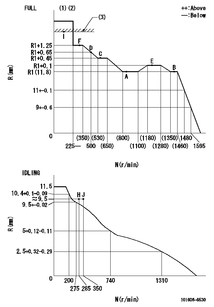
Test data Ex:
Governor adjustment

N:Pump speed
R:Rack position (mm)
(1)Torque cam stamping: T1
(2)Tolerance for racks not indicated: +-0.05mm.
(3)RACK LIMIT
----------
T1=D91
----------
----------
T1=D91
----------
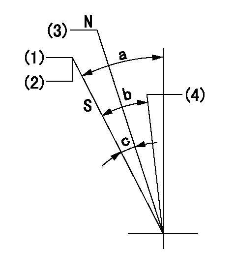
Speed control lever angle

F:Full speed
I:Idle
(1)Stopper bolt setting
----------
----------
a=18.5deg+-5deg b=(37.5deg)+-3deg
----------
----------
a=18.5deg+-5deg b=(37.5deg)+-3deg
Stop lever angle

N:Engine manufacturer's normal use
S:Stop the pump.
(1)Set the stopper bolt at speed = aa and rack position = bb and confirm non-injection.
(2)After setting the stopper bolt, confirm non-injection at speed cc. Rack position = dd (non-injection rack position).
(3)Rack position = approximately ee.
(4)Free (at shipping)
----------
aa=1400r/min bb=7.2-0.5mm cc=275r/min dd=(8.5)mm ee=15mm
----------
a=38.5deg+-5deg b=(27deg) c=15.5deg+-5deg
----------
aa=1400r/min bb=7.2-0.5mm cc=275r/min dd=(8.5)mm ee=15mm
----------
a=38.5deg+-5deg b=(27deg) c=15.5deg+-5deg
0000001501 MICRO SWITCH
Adjustment of the micro-switch
Adjust the bolt to obtain the following lever position when the micro-switch is ON.
(1)Speed N1
(2)Rack position Ra
----------
N1=400r/min Ra=9.6+-0.1mm
----------
----------
N1=400r/min Ra=9.6+-0.1mm
----------
Timing setting

(1)Pump vertical direction
(2)Position of timer's tooth at No 1 cylinder's beginning of injection
(3)B.T.D.C.: aa
(4)-
----------
aa=12deg
----------
a=(1deg)
----------
aa=12deg
----------
a=(1deg)
Information:
Table 4
Cat Specification for Neat (B100) Biodiesel Blending Fuel
Property Test Method, United States Test Method, International Units Limits, B100 Blending Fuel
Density at 15°C “ASTM D1298” “ISO 3675” g/cm3 0.86-0.90
Viscosity at 40°C “ASTM D445” “ISO 3104” mm2/s (cSt) 1.9-6.0
Flash Point “ASTM D93” “ISO 3679” °C 93 minimum
Pour Point - - - 6 °C (10 °F) minimum below ambient temperature
- Summer “ASTM D97” “ISO 3016” °C
- Winter
Cloud Point “ASTM D2500” °C Report
Sulfur Content(1) “ASTM D5453” “ISO 20846” “ISO 20884” percent weight 0.0015(2) maximum
Distillation - - - -
T90 “ASTM D86” “ISO 3924” °C 360
Cetane Number “ASTM D613” “ISO 5165” % evaporation 45 minimum
Sulfated Ash “ASTM D874” “ISO 3987” or "ISO 6245" percent weight 0.02 maximum
Water and Sediment “ASTM D2709” “ISO 12937” percent volume 0.05 maximum
Water "ASTM D1796" "EN ISO 12937" % m/m -
Copper Corrosion, 3 hours at 50oC “ASTM D130” “ISO 2160” - No. 1
Oxidation Stability “EN 14112” or "EN 15751" “EN 14112” or "EN 15751" hours 3 minimum
Ramsbottom Carbon Residue on 10% bottoms "ASTM D524" “ISO 10370” %-m/m 0.30 maximum
Carbon Residue, Conradson (CCR) “ASTM D4530” - percent weight 0.05 maximum
Esterification "ASTM D 7806" or "ASTM D 7371" “EN 14103” percent volume 97.5 minimum
Total Acid Number “ASTM D664” “EN 14104” mg KOH/g 0.5 maximum
Methanol Content “EN 14110” “EN 14110” percent weight 0.2 maximum
Monoglycerides “ASTM D6584” “EN 14105” percent weight 0.8 maximum
Diglycerides “ASTM D6584” “EN 14105” percent weight 0.2 maximum
Triglycerides “ASTM D6584” “EN 14105” percent weight 0.2 maximum
Free Glycerin “ASTM D6584” “EN 14105” percent weight 0.02 maximum
Total Glycerin “ASTM D6584” “EN 14105” percent weight 0.240 maximum
Phosphorus Content “ASTM D4951” “EN 14107” percent weight 0.001 maximum
Calcium plus Magnesium “EN 14538” “EN 14538” ppm 5 maximum
Sodium plus Potassium “EN 14538” “EN 14538” ppm 5 maximum
Cold Soak Filterability “ASTM D7501” – seconds 360 maximum
Cleanliness “ASTM D7619” “ISO 4406” – (3)
Total contamination "EN 12662" "EN 12662" mg/kg 24 maximum
Appearance "ASTM D4176" - - Clear and Bright
(1) Methods for testing S are based on the sulfur content in diesel fuel used for blending. Consult with the fuel supplier and ensure the correct method has been used
(2) Sulfur level must be per local regulations. Higher S levels may be used where allowed.
(3) Recommended cleanliness level for fuel as dispensed into the engine fuel tank is ISO 18/16/13 or cleaner per the test methods listed. Refer to the contamination control Chapter for more details.Note: Fuels that meet the most current revision level of "ASTM D6751" or "EN 14214" may be used for blending with an acceptable distillate fuel. The conditions, recommendations, and limits that are noted in this Biodiesel section apply.Referenced Documents
Refer to the “Reference Material - Fuel” section of this Special Publication for the reference material for the information in this section.