Information injection-pump assembly
BOSCH
9 400 615 518
9400615518
ZEXEL
101606-6510
1016066510
MITSUBISHI
ME076487
me076487
Rating:
Include in #1:
101402-4720
as _
Cross reference number
BOSCH
9 400 615 518
9400615518
ZEXEL
101606-6510
1016066510
MITSUBISHI
ME076487
me076487
Zexel num
Bosch num
Firm num
Name
Calibration Data:
Adjustment conditions
Test oil
1404 Test oil ISO4113 or {SAEJ967d}
1404 Test oil ISO4113 or {SAEJ967d}
Test oil temperature
degC
40
40
45
Nozzle and nozzle holder
105780-8140
Bosch type code
EF8511/9A
Nozzle
105780-0000
Bosch type code
DN12SD12T
Nozzle holder
105780-2080
Bosch type code
EF8511/9
Opening pressure
MPa
17.2
Opening pressure
kgf/cm2
175
Injection pipe
Outer diameter - inner diameter - length (mm) mm 6-2-600
Outer diameter - inner diameter - length (mm) mm 6-2-600
Overflow valve
131424-5520
Overflow valve opening pressure
kPa
255
221
289
Overflow valve opening pressure
kgf/cm2
2.6
2.25
2.95
Tester oil delivery pressure
kPa
157
157
157
Tester oil delivery pressure
kgf/cm2
1.6
1.6
1.6
Direction of rotation (viewed from drive side)
Left L
Left L
Injection timing adjustment
Direction of rotation (viewed from drive side)
Left L
Left L
Injection order
1-5-3-6-
2-4
Pre-stroke
mm
3.8
3.75
3.85
Beginning of injection position
Governor side NO.1
Governor side NO.1
Difference between angles 1
Cal 1-5 deg. 60 59.5 60.5
Cal 1-5 deg. 60 59.5 60.5
Difference between angles 2
Cal 1-3 deg. 120 119.5 120.5
Cal 1-3 deg. 120 119.5 120.5
Difference between angles 3
Cal 1-6 deg. 180 179.5 180.5
Cal 1-6 deg. 180 179.5 180.5
Difference between angles 4
Cyl.1-2 deg. 240 239.5 240.5
Cyl.1-2 deg. 240 239.5 240.5
Difference between angles 5
Cal 1-4 deg. 300 299.5 300.5
Cal 1-4 deg. 300 299.5 300.5
Injection quantity adjustment
Adjusting point
-
Rack position
11.8
Pump speed
r/min
850
850
850
Each cylinder's injection qty
mm3/st.
71.3
69.2
73.4
Basic
*
Fixing the rack
*
Standard for adjustment of the maximum variation between cylinders
*
Injection quantity adjustment_02
Adjusting point
H
Rack position
9.5+-0.5
Pump speed
r/min
285
285
285
Each cylinder's injection qty
mm3/st.
11.9
10.1
13.7
Fixing the rack
*
Standard for adjustment of the maximum variation between cylinders
*
Injection quantity adjustment_03
Adjusting point
A
Rack position
R1(11.8)
Pump speed
r/min
850
850
850
Average injection quantity
mm3/st.
71.3
70.3
72.3
Basic
*
Fixing the lever
*
Injection quantity adjustment_04
Adjusting point
B
Rack position
R1(11.8)
Pump speed
r/min
1400
1400
1400
Average injection quantity
mm3/st.
80.9
76.9
84.9
Fixing the lever
*
Injection quantity adjustment_05
Adjusting point
D
Rack position
R1+0.65
Pump speed
r/min
500
500
500
Average injection quantity
mm3/st.
70.4
66.4
74.4
Fixing the lever
*
Injection quantity adjustment_06
Adjusting point
F
Rack position
R1+1.25
Pump speed
r/min
300
300
300
Average injection quantity
mm3/st.
69.5
65.5
73.5
Fixing the lever
*
Injection quantity adjustment_07
Adjusting point
I
Rack position
14.3+-0.
5
Pump speed
r/min
100
100
100
Average injection quantity
mm3/st.
108
88
128
Fixing the lever
*
Rack limit
*
Timer adjustment
Pump speed
r/min
1150
Advance angle
deg.
0.5
Timer adjustment_02
Pump speed
r/min
1250
Advance angle
deg.
2.5
2
3
Timer adjustment_03
Pump speed
r/min
1350
Advance angle
deg.
5
4.5
5.5
Remarks
Finish
Finish
Test data Ex:
Governor adjustment
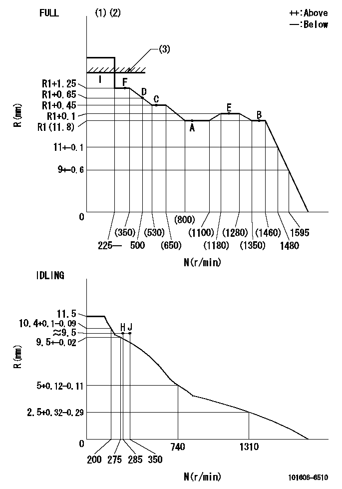
N:Pump speed
R:Rack position (mm)
(1)Torque cam stamping: T1
(2)Tolerance for racks not indicated: +-0.05mm.
(3)RACK LIMIT
----------
T1=D91
----------
----------
T1=D91
----------
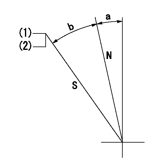
Speed control lever angle

F:Full speed
I:Idle
(1)Stopper bolt set position 'H'
----------
----------
a=18.5deg+-5deg b=(37.5deg)+-3deg
----------
----------
a=18.5deg+-5deg b=(37.5deg)+-3deg
Stop lever angle
N:Pump normal
S:Stop the pump.
(1)Set the stopper bolt at pump speed = aa and rack position = bb (non-injection rack position). Confirm non-injection.
(2)After setting the stopper bolt, confirm non-injection at speed cc. Rack position = dd (non-injection rack position).
----------
aa=1400r/min bb=7.2-0.5mm cc=275r/min dd=(8.5)-0.5mm
----------
a=11.5deg+-5deg b=27deg+-5deg
----------
aa=1400r/min bb=7.2-0.5mm cc=275r/min dd=(8.5)-0.5mm
----------
a=11.5deg+-5deg b=27deg+-5deg
0000001501 MICRO SWITCH
Adjustment of the micro-switch
Adjust the bolt to obtain the following lever position when the micro-switch is ON.
(1)Speed N1
(2)Rack position Ra
----------
N1=400r/min Ra=9.6+-0.1mm
----------
----------
N1=400r/min Ra=9.6+-0.1mm
----------
0000001601 RACK SENSOR

V1:Supply voltage
V2f:Full side output voltage
V2i:Idle side output voltage
(A) Black
(B) Yellow
(C) Red
(D) Trimmer
(E): Shaft
(F) Nut
(G) Load lever
1. Load sensor adjustment
(1)Connect as shown in the above diagram and apply supply voltage V1.
(2)Hold the load lever (G) against the full side.
(3)Turn the shaft so that the voltage between (A) and (B) is V2.
(4)Hold the load lever (G) against the idle side.
(5)Adjust (D) so that the voltage between (A) and (B) is V2i.
(6)Repeat the above adjustments.
(7)Tighten the nut (F) at the point satisfying the standards.
(8)Hold the load lever against the full side stopper and the idle side stopper.
(9)At this time, confirm that the full side output voltage is V2f and the idle side output voltage is V2i.
----------
V1=3.57+-0.02V V2f=3+0.05V V2i=1+0.1V
----------
----------
V1=3.57+-0.02V V2f=3+0.05V V2i=1+0.1V
----------
Timing setting

(1)Pump vertical direction
(2)Position of timer's tooth at No 1 cylinder's beginning of injection
(3)B.T.D.C.: aa
(4)-
----------
aa=12deg
----------
a=(1deg)
----------
aa=12deg
----------
a=(1deg)
Information:
1. Remove suction bell (3) and tubes, oil supply tube (2) and BrakeSaver oil supply tube (1) from the engine block and oil pump. 2. Remove three bolts (5) and oil pump (4) from the engine. The following steps are for the installation of the oil pump.3. Put oil pump (4) in position on the engine. Make sure the oil pump gear is engaged with the crankshaft gear, and install three bolts (5) that hold the oil pump.4. Put clean engine oil on the O-ring seals on the oil tubes.5. Install suction bell (3) and tubes, oil supply tube (2) BrakeSaver oil supply tube (1).End By:a. install oil pan (BrakeSaver)Disassemble Oil Pump (BrakeSaver)
Start By:a. remove oil pump (BrakeSaver) 1. Remove the bolt and washer that hold drive gear (1) on the shaft.2. Use tooling (A) to remove drive gear (1) from the shaft. Remove the key from the shaft. Put alignment marks on the pump bodies so they can be assembled in the correct position. 3. Remove retainer (3) from the bypass valve. Remove the spring and bypass valve.4. Remove bolts (4) that hold pump body (2) to the main pump body. Remove pump body (2).5. Use tooling (B) to remove the bearings from pump body (2). 6. Remove gears (7). Put identification marks on the gears so they can be assembled in the same position.7. Remove spacer (6) from the main oil pump body (5). Use tooling (B) to remove the bearings from spacer (6).8. Remove the gears from main oil pump body (5). 9. Use tooling (B) to remove the bearings from the main oil pump body.Assemble Oil Pump (BrakeSaver)
1. Use tooling (B) to install bearings (8) until they are even with the outside surface of main oil pump body (5). Install bearings (8) so the joints in the bearings are 30° 15° from the center line of the bearing bores and toward the oil pump outlet passage as shown. 2. Use tooling (B) to install bearings (9) in the spacer. Install the bearings until they are in position an equal distance in from each side of the spacer. Install the bearings with the oil holes in the bearings in alignment with the oil holes in the spacer and the joints in the bearings in alignment with the cavity on the spacer as shown. 3. Put clean engine oil on all the gears and bearings before they are assembled in the oil pump. Install idler and drive gears (10) in the main oil pump body.4. Install spacer (6) on the gear shafts with the smaller cavity out and the oil holes in the spacer toward the pump outlet passage as shown. 5. Use tooling (B) to install bearings (11) in pump body (2) until they are 1.52 0.25 (.060 .010 in.) from the inside edge of the bearing bores. Install the bearings so the joints in the bearings are 30° 15° from the centerline of the bearing bores and toward the outer