Information injection-pump assembly
BOSCH
9 400 615 517
9400615517
ZEXEL
101606-6501
1016066501
MITSUBISHI
ME070929
me070929

Rating:
Service parts 101606-6501 INJECTION-PUMP ASSEMBLY:
1.
_
6.
COUPLING PLATE
7.
COUPLING PLATE
8.
_
9.
_
11.
Nozzle and Holder
ME047437
12.
Open Pre:MPa(Kqf/cm2)
17.7{180}

15.
NOZZLE SET
Cross reference number
BOSCH
9 400 615 517
9400615517
ZEXEL
101606-6501
1016066501
MITSUBISHI
ME070929
me070929
Zexel num
Bosch num
Firm num
Name
101606-6501
9 400 615 517
ME070929 MITSUBISHI
INJECTION-PUMP ASSEMBLY
6D16T * K 14BF INJECTION PUMP ASSY PE6AD PE
6D16T * K 14BF INJECTION PUMP ASSY PE6AD PE
Calibration Data:
Adjustment conditions
Test oil
1404 Test oil ISO4113 or {SAEJ967d}
1404 Test oil ISO4113 or {SAEJ967d}
Test oil temperature
degC
40
40
45
Nozzle and nozzle holder
105780-8140
Bosch type code
EF8511/9A
Nozzle
105780-0000
Bosch type code
DN12SD12T
Nozzle holder
105780-2080
Bosch type code
EF8511/9
Opening pressure
MPa
17.2
Opening pressure
kgf/cm2
175
Injection pipe
Outer diameter - inner diameter - length (mm) mm 6-2-600
Outer diameter - inner diameter - length (mm) mm 6-2-600
Overflow valve
131424-5520
Overflow valve opening pressure
kPa
255
221
289
Overflow valve opening pressure
kgf/cm2
2.6
2.25
2.95
Tester oil delivery pressure
kPa
255
255
255
Tester oil delivery pressure
kgf/cm2
2.6
2.6
2.6
Direction of rotation (viewed from drive side)
Left L
Left L
Injection timing adjustment
Direction of rotation (viewed from drive side)
Left L
Left L
Injection order
1-5-3-6-
2-4
Pre-stroke
mm
4.2
4.15
4.25
Beginning of injection position
Governor side NO.1
Governor side NO.1
Difference between angles 1
Cal 1-5 deg. 60 59.5 60.5
Cal 1-5 deg. 60 59.5 60.5
Difference between angles 2
Cal 1-3 deg. 120 119.5 120.5
Cal 1-3 deg. 120 119.5 120.5
Difference between angles 3
Cal 1-6 deg. 180 179.5 180.5
Cal 1-6 deg. 180 179.5 180.5
Difference between angles 4
Cyl.1-2 deg. 240 239.5 240.5
Cyl.1-2 deg. 240 239.5 240.5
Difference between angles 5
Cal 1-4 deg. 300 299.5 300.5
Cal 1-4 deg. 300 299.5 300.5
Injection quantity adjustment
Adjusting point
A
Rack position
9.8
Pump speed
r/min
1400
1400
1400
Average injection quantity
mm3/st.
94.8
93.8
95.8
Max. variation between cylinders
%
0
-2.5
2.5
Basic
*
Fixing the lever
*
Injection quantity adjustment_02
Adjusting point
E
Rack position
8.1+-0.5
Pump speed
r/min
340
340
340
Average injection quantity
mm3/st.
13.8
12.3
15.3
Max. variation between cylinders
%
0
-15
15
Fixing the rack
*
Timer adjustment
Pump speed
r/min
1050--
Advance angle
deg.
0
0
0
Remarks
Start
Start
Timer adjustment_02
Pump speed
r/min
1000
Advance angle
deg.
0.5
Timer adjustment_03
Pump speed
r/min
1400
Advance angle
deg.
3
2.5
3.5
Remarks
Finish
Finish
Test data Ex:
Governor adjustment
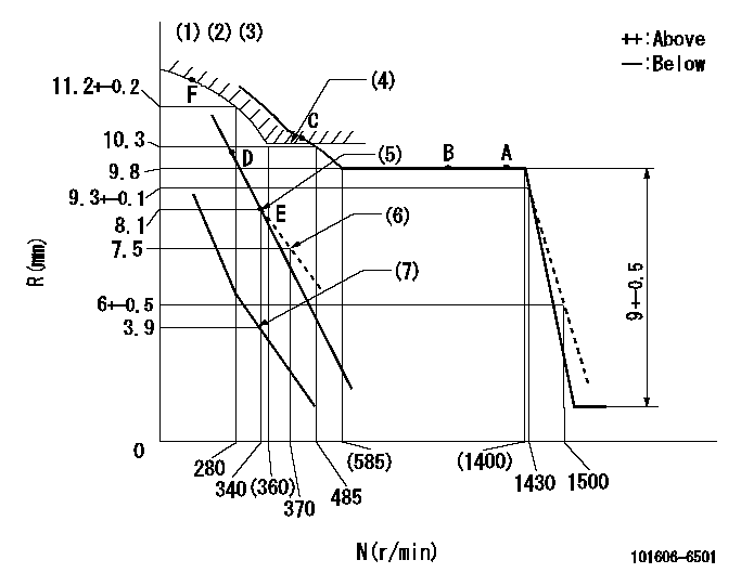
N:Pump speed
R:Rack position (mm)
(1)Lever ratio: RT
(2)Target shim dimension: TH
(3)Tolerance for racks not indicated: +-0.05mm.
(4)Excess fuel setting for starting: SXL
(5)Main spring setting
(6)Damper spring setting
(7)Set idle sub-spring
----------
RT=1 TH=2.7mm SXL=10.7+-0.1mm
----------
----------
RT=1 TH=2.7mm SXL=10.7+-0.1mm
----------
Speed control lever angle

F:Full speed
I:Idle
(1)Stopper bolt setting
----------
----------
a=(20deg)+-5deg b=(3deg)+-5deg
----------
----------
a=(20deg)+-5deg b=(3deg)+-5deg
0000000901
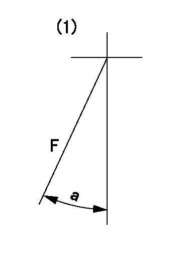
F:Full load
(1)Fix the lever at the full load position
----------
----------
a=16deg+-5deg
----------
----------
a=16deg+-5deg
Stop lever angle
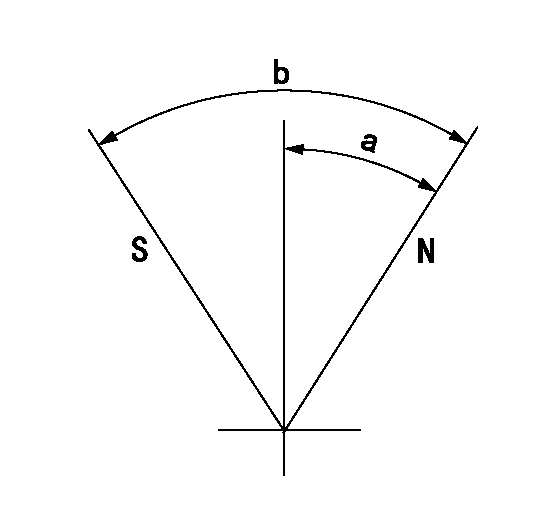
N:Pump normal
S:Stop the pump.
----------
----------
a=20deg+-5deg b=71deg+-5deg
----------
----------
a=20deg+-5deg b=71deg+-5deg
Timing setting

(1)Pump vertical direction
(2)Position of timer's tooth at No 1 cylinder's beginning of injection
(3)B.T.D.C.: aa
(4)-
----------
aa=14deg
----------
a=(1deg)
----------
aa=14deg
----------
a=(1deg)
Information:
5. Install a 3/8" - 16 NC forged eyebolt in the top of the BrakeSaver housing, and fasten a hoist to it.6. Install tooling (A) on the BrakeSaver housing and rotor. Tooling (A) holds the BrakeSaver housing and rotor assembly together at removal. This prevents damage to the rotor rings and seals.7. Remove bolts (6) that hold BrakeSaver housing (7) to the flywheel housing.8. Use bolts (4) as forcing screws, and tighten the bolts evenly to remove BrakeSaver housing (7) from the flywheel housing. The weight is 86 kg (190 lb.)Install BrakeSaver
1. Install tooling (A) on the BrakeSaver housing and rotor. Tooling (A) holds the BrakeSaver housing and rotor assembly together at installation. This prevents damage to the rotor rings and seals.2. Install a 3/8" - 16 NC forged eyebolt in the top of the BrakeSaver housing, and fasten a hoist to it.3. Install two 5/8" - 18 NC guide bolts (9) in the crankshaft as shown. Make sure dowel (8) is in alignment with the dowel hole in the rear assembly, and put BrakeSaver housing (7) in position in the flywheel housing.4. Install the three bolts that hold the BrakeSaver housing to the flywheel housing. Remove tooling (A) and guide pins (9). 5. Connect the oil line to fitting (5).6. Inspect the O-ring seals for damage, and make replacements if needed. Install O-ring seals (10) and (11). Put clean engine oil on the O-ring seals.7. Install manifold (12) into the BrakeSaver control valve, and install the four bolts that hold the manifold to the BrakeSaver housing. 8. Connect BrakeSaver lubrication oil line (1) to the fitting in the BrakeSaver housing.End By:a. install flywheel (BrakeSaver)Disassemble BrakeSaver
Start By:a. remove BrakeSaver1. Remove tooling (A) from BrakeSaver housing and rotor. Tooling (A) prevents damage to the rotor seals and rings during removal of the BrakeSaver housing. 2. Remove bolts (1) from gear plate (2). Remove the plate. 3. Put alignment marks on stator (3) and housing (4) for assembly purposes. Remove bolts (5) and the stator. 4. Turn the stator over, and remove spiral ring (6). 5. Turn the stator over again. Remove sleeve assembly (9). Remove O-ring seal (7) and lip-type seal (8) from the sleeve. 6. Remove O-ring seal (11) and the six smaller O-ring seals from the oil holes on the housing.7. Remove rotor assembly (12).8. Remove seal ring (10) from both sides of the rotor. 9. Remove carrier (13) and wear sleeve (14) with tooling (B) from both sides of the rotor. 10. Remove spiral ring (15). Turn the housing over, and remove sleeve assembly (17). Remove the lip-type seal and O-ring seal (16) from the sleeve.Assemble BrakeSaver
1. Inspect the O-ring seals for damage, and make replacements if needed. Put clean engine oil on the O-ring seals. 2. Install O-ring seal (16) on sleeve (17).3. Install the sleeve in the BrakeSaver housing. Make an alignment of the notch (18) on the sleeve with the notch in the housing, and install the dowel.
Make certain there is clearance behind
Have questions with 101606-6501?
Group cross 101606-6501 ZEXEL
Mitsubishi
101606-6501
9 400 615 517
ME070929
INJECTION-PUMP ASSEMBLY
6D16T
6D16T