Information injection-pump assembly
BOSCH
9 400 615 495
9400615495
ZEXEL
101606-6170
1016066170
MITSUBISHI
ME076263
me076263
Rating:
Include in #1:
101402-4500
as _
Cross reference number
BOSCH
9 400 615 495
9400615495
ZEXEL
101606-6170
1016066170
MITSUBISHI
ME076263
me076263
Zexel num
Bosch num
Firm num
Name
101606-6170
9 400 615 495
ME076263 MITSUBISHI
INJECTION-PUMP ASSEMBLY
6D14 * K
6D14 * K
Calibration Data:
Adjustment conditions
Test oil
1404 Test oil ISO4113 or {SAEJ967d}
1404 Test oil ISO4113 or {SAEJ967d}
Test oil temperature
degC
40
40
45
Nozzle and nozzle holder
105780-8140
Bosch type code
EF8511/9A
Nozzle
105780-0000
Bosch type code
DN12SD12T
Nozzle holder
105780-2080
Bosch type code
EF8511/9
Opening pressure
MPa
17.2
Opening pressure
kgf/cm2
175
Injection pipe
Outer diameter - inner diameter - length (mm) mm 6-2-600
Outer diameter - inner diameter - length (mm) mm 6-2-600
Overflow valve
131424-5520
Overflow valve opening pressure
kPa
255
221
289
Overflow valve opening pressure
kgf/cm2
2.6
2.25
2.95
Tester oil delivery pressure
kPa
157
157
157
Tester oil delivery pressure
kgf/cm2
1.6
1.6
1.6
Direction of rotation (viewed from drive side)
Left L
Left L
Injection timing adjustment
Direction of rotation (viewed from drive side)
Left L
Left L
Injection order
1-5-3-6-
2-4
Pre-stroke
mm
3.3
3.25
3.35
Beginning of injection position
Governor side NO.1
Governor side NO.1
Difference between angles 1
Cal 1-5 deg. 60 59.5 60.5
Cal 1-5 deg. 60 59.5 60.5
Difference between angles 2
Cal 1-3 deg. 120 119.5 120.5
Cal 1-3 deg. 120 119.5 120.5
Difference between angles 3
Cal 1-6 deg. 180 179.5 180.5
Cal 1-6 deg. 180 179.5 180.5
Difference between angles 4
Cyl.1-2 deg. 240 239.5 240.5
Cyl.1-2 deg. 240 239.5 240.5
Difference between angles 5
Cal 1-4 deg. 300 299.5 300.5
Cal 1-4 deg. 300 299.5 300.5
Injection quantity adjustment
Adjusting point
-
Rack position
11
Pump speed
r/min
850
850
850
Each cylinder's injection qty
mm3/st.
65
63
67
Basic
*
Fixing the rack
*
Standard for adjustment of the maximum variation between cylinders
*
Injection quantity adjustment_02
Adjusting point
H
Rack position
9.5+-0.5
Pump speed
r/min
275
275
275
Each cylinder's injection qty
mm3/st.
10.5
9
12
Fixing the rack
*
Standard for adjustment of the maximum variation between cylinders
*
Injection quantity adjustment_03
Adjusting point
A
Rack position
R1(11)
Pump speed
r/min
850
850
850
Average injection quantity
mm3/st.
65
64
66
Basic
*
Fixing the lever
*
Injection quantity adjustment_04
Adjusting point
B
Rack position
R1(11)
Pump speed
r/min
1450
1450
1450
Average injection quantity
mm3/st.
77.5
75.5
79.5
Fixing the lever
*
Injection quantity adjustment_05
Adjusting point
C
Rack position
R1+0.4
Pump speed
r/min
600
600
600
Average injection quantity
mm3/st.
59.7
55.7
63.7
Fixing the lever
*
Injection quantity adjustment_06
Adjusting point
I
Rack position
-
Pump speed
r/min
100
100
100
Average injection quantity
mm3/st.
90
70
110
Fixing the lever
*
Rack limit
*
Timer adjustment
Pump speed
r/min
1250--
Advance angle
deg.
0
0
0
Remarks
Start
Start
Timer adjustment_02
Pump speed
r/min
1200
Advance angle
deg.
0.5
Timer adjustment_03
Pump speed
r/min
1350
Advance angle
deg.
2.4
1.9
2.9
Timer adjustment_04
Pump speed
r/min
1500
Advance angle
deg.
5
4.5
5.5
Remarks
Finish
Finish
Test data Ex:
Governor adjustment
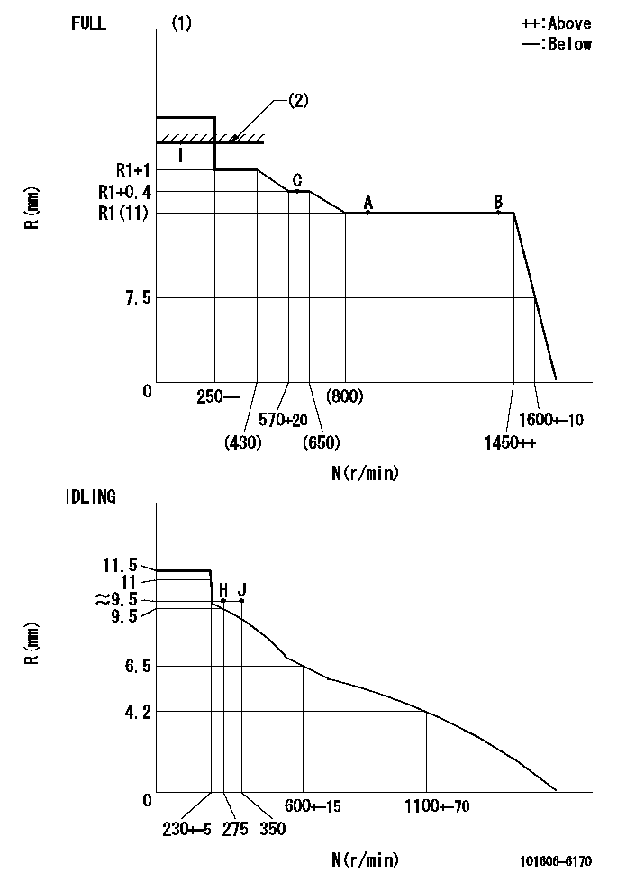
N:Pump speed
R:Rack position (mm)
(1)Torque cam stamping: T1
(2)RACK LIMIT
----------
T1=C67
----------
----------
T1=C67
----------
Speed control lever angle

F:Full speed
I:Idle
(1)Use the hole at R = aa
(2)Stopper bolt set position 'H'
----------
aa=40mm
----------
a=18.5deg+-5deg b=40.5deg+-3deg
----------
aa=40mm
----------
a=18.5deg+-5deg b=40.5deg+-3deg
Stop lever angle

N:Engine manufacturer's normal use
S:Stop the pump.
(1)Set the stopper bolt at speed = rated point and rack position = aa (non-injection rack position). Confirm non-injection.
(2)After setting the stopper bolt , confirm non-injection at pump speed bb. Rack position = cc (non-injection rack position).
(3)Rack position = approximately dd
(4)Free (at shipping)
----------
aa=5.4-0.5mm bb=275r/min cc=(7.4)mm dd=15mm
----------
a=41deg+-5deg b=(29.5deg) c=15.5deg+-3deg
----------
aa=5.4-0.5mm bb=275r/min cc=(7.4)mm dd=15mm
----------
a=41deg+-5deg b=(29.5deg) c=15.5deg+-3deg
0000001501 MICRO SWITCH
Adjustment of the micro-switch
Adjust the bolt to obtain the following lever position when the micro-switch is ON.
(1)Speed N1
(2)Rack position Ra
----------
N1=400+-5r/min Ra=9.2mm
----------
----------
N1=400+-5r/min Ra=9.2mm
----------
Timing setting

(1)Pump vertical direction
(2)Position of timer's tooth at No 1 cylinder's beginning of injection
(3)B.T.D.C.: aa
(4)-
----------
aa=13deg
----------
a=(0deg)
----------
aa=13deg
----------
a=(0deg)
Information:
Guidelines For Reusable Parts; Valves And Valve Springs, Forms SEBF8002 and SEBF8034 have the procedure and specifications necessary for checking used valves and valve springs.(1) Springs (Inner And Outer):Inner Valve Spring (4W2472): Assembled length ... 50.24 mm (1.978 in)Load at assembled length ... 178 18 N (40.1 4.1 lb)Operating length (min) ... 35.97 mm (1.416 in)Load at min operating length ... 343 17 N (77.2 3.8 lb)Free length after test ... 65.7 mm (2.60 in)Outside diameter ... 25.13 mm (.989 in)Outer Valve Spring (4W2471): Assembled length ... 53.24 mm (2.096 in)Load at assembled length ... 245 24 N (55.1 5.4 lb)Operating length (min) ... 38.96 mm (1.534 in) Load at min operating length ... 805 40 N (181.1 9.0 lb)Free length after test ... 59.5 mm (2.34 in)Outside diameter ... 37.31 mm (1.469 in) The following springs (inner and outer) are used on the exhaust valves with the 70 PSI Williams Blue-Ox Exhaust Brake.Inner Valve Spring (9Y3327): Assembled length ... 50.24 mm (1.978 in)Load at assembled length ... 264 26 N (59.4 5.9 lb)Operating length (min) ... 36.14 mm (1.423 in)Load at min operating length ... 445 22 N (100.1 5.0 lb)Free length after test ... 70.9 mm (2.79 in)Outside diameter ... 29.83 mm (1.174 in)Outer Valve Spring (9Y3326): Assembled length ... 53.24 mm (2.096 in)Load at assembled length ... 521 52 N (117.2 11.7 lb)Operating length (min) ... 38.96 mm (1.534 in)Load at min operating length ... 992 50 N (223.2 11.3 lb)Free length after test ... 69.04 mm (2.718 in)Outside diameter ... 42.61 mm (1.678 in)(2) Height to top of valve guide ... 32.3 0.8 mm (1.27 .03 in)(3) Diameter of valve stem (new) ... 9.441 0.008 mm (.3717 .0003 in) Coat the intake and exhaust valve stems with 8T2998 Camshaft Lubricant prior to installation in the cylinder head.Use again minimum:1W3860 Exhaust ... 9.408 mm (.3704 in)2W2622 Intake ... 9.408 mm (.3704 in)Bore in valve guide with guide installed in the head (new) ... 9.487
Have questions with 101606-6170?
Group cross 101606-6170 ZEXEL
Mitsubishi
101606-6170
9 400 615 495
ME076263
INJECTION-PUMP ASSEMBLY
6D14
6D14