Information injection-pump assembly
BOSCH
9 400 615 492
9400615492
ZEXEL
101606-6140
1016066140
MITSUBISHI
ME076260
me076260
Rating:
Include in #1:
101402-4480
as _
Cross reference number
BOSCH
9 400 615 492
9400615492
ZEXEL
101606-6140
1016066140
MITSUBISHI
ME076260
me076260
Zexel num
Bosch num
Firm num
Name
101606-6140
9 400 615 492
ME076260 MITSUBISHI
INJECTION-PUMP ASSEMBLY
6D14 * K
6D14 * K
Calibration Data:
Adjustment conditions
Test oil
1404 Test oil ISO4113 or {SAEJ967d}
1404 Test oil ISO4113 or {SAEJ967d}
Test oil temperature
degC
40
40
45
Nozzle and nozzle holder
105780-8140
Bosch type code
EF8511/9A
Nozzle
105780-0000
Bosch type code
DN12SD12T
Nozzle holder
105780-2080
Bosch type code
EF8511/9
Opening pressure
MPa
17.2
Opening pressure
kgf/cm2
175
Injection pipe
Outer diameter - inner diameter - length (mm) mm 6-2-600
Outer diameter - inner diameter - length (mm) mm 6-2-600
Overflow valve
131424-5520
Overflow valve opening pressure
kPa
255
221
289
Overflow valve opening pressure
kgf/cm2
2.6
2.25
2.95
Tester oil delivery pressure
kPa
157
157
157
Tester oil delivery pressure
kgf/cm2
1.6
1.6
1.6
Direction of rotation (viewed from drive side)
Left L
Left L
Injection timing adjustment
Direction of rotation (viewed from drive side)
Left L
Left L
Injection order
1-5-3-6-
2-4
Pre-stroke
mm
3.3
3.25
3.35
Beginning of injection position
Governor side NO.1
Governor side NO.1
Difference between angles 1
Cal 1-5 deg. 60 59.5 60.5
Cal 1-5 deg. 60 59.5 60.5
Difference between angles 2
Cal 1-3 deg. 120 119.5 120.5
Cal 1-3 deg. 120 119.5 120.5
Difference between angles 3
Cal 1-6 deg. 180 179.5 180.5
Cal 1-6 deg. 180 179.5 180.5
Difference between angles 4
Cyl.1-2 deg. 240 239.5 240.5
Cyl.1-2 deg. 240 239.5 240.5
Difference between angles 5
Cal 1-4 deg. 300 299.5 300.5
Cal 1-4 deg. 300 299.5 300.5
Injection quantity adjustment
Adjusting point
-
Rack position
11
Pump speed
r/min
850
850
850
Each cylinder's injection qty
mm3/st.
65
63
67
Basic
*
Fixing the rack
*
Standard for adjustment of the maximum variation between cylinders
*
Injection quantity adjustment_02
Adjusting point
H
Rack position
9.5+-0.5
Pump speed
r/min
275
275
275
Each cylinder's injection qty
mm3/st.
10.5
9
12
Fixing the rack
*
Standard for adjustment of the maximum variation between cylinders
*
Injection quantity adjustment_03
Adjusting point
A
Rack position
R1(11)
Pump speed
r/min
850
850
850
Average injection quantity
mm3/st.
65
64
66
Basic
*
Fixing the lever
*
Injection quantity adjustment_04
Adjusting point
B
Rack position
R1(11)
Pump speed
r/min
1450
1450
1450
Average injection quantity
mm3/st.
77.5
75.5
79.5
Fixing the lever
*
Injection quantity adjustment_05
Adjusting point
C
Rack position
R1+0.4
Pump speed
r/min
600
600
600
Average injection quantity
mm3/st.
59.7
55.7
63.7
Fixing the lever
*
Injection quantity adjustment_06
Adjusting point
I
Rack position
-
Pump speed
r/min
100
100
100
Average injection quantity
mm3/st.
90
70
110
Fixing the lever
*
Rack limit
*
Timer adjustment
Pump speed
r/min
1250--
Advance angle
deg.
0
0
0
Remarks
Start
Start
Timer adjustment_02
Pump speed
r/min
1200
Advance angle
deg.
0.5
Timer adjustment_03
Pump speed
r/min
1350
Advance angle
deg.
2.4
1.9
2.9
Timer adjustment_04
Pump speed
r/min
1500
Advance angle
deg.
5
4.5
5.5
Remarks
Finish
Finish
Test data Ex:
Governor adjustment
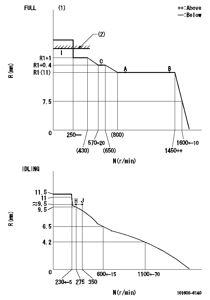
N:Pump speed
R:Rack position (mm)
(1)Torque cam stamping: T1
(2)RACK LIMIT
----------
T1=C67
----------
----------
T1=C67
----------
Speed control lever angle

F:Full speed
I:Idle
(1)Use the hole at R = aa
(2)Stopper bolt set position 'H'
----------
aa=40mm
----------
a=18.5deg+-5deg b=40.5deg+-3deg
----------
aa=40mm
----------
a=18.5deg+-5deg b=40.5deg+-3deg
Stop lever angle

N:Engine manufacturer's normal use
S:Stop the pump.
(1)Set the stopper bolt at speed = rated point and rack position = aa (non-injection rack position). Confirm non-injection.
(2)After setting the stopper bolt , confirm non-injection at pump speed bb. Rack position = cc (non-injection rack position).
(3)Rack position = approximately dd
(4)Free (at shipping)
----------
aa=5.4-0.5mm bb=275r/min cc=(7.4)mm dd=17.4mm
----------
a=38.5deg+-5deg b=(27deg) c=17deg+-5deg
----------
aa=5.4-0.5mm bb=275r/min cc=(7.4)mm dd=17.4mm
----------
a=38.5deg+-5deg b=(27deg) c=17deg+-5deg
0000001501 MICRO SWITCH
Adjustment of the micro-switch
Adjust the bolt to obtain the following lever position when the micro-switch is ON.
(1)Speed N1
(2)Rack position Ra
----------
N1=400+-5r/min Ra=9.2mm
----------
----------
N1=400+-5r/min Ra=9.2mm
----------
Timing setting

(1)Pump vertical direction
(2)Position of timer's tooth at No 1 cylinder's beginning of injection
(3)B.T.D.C.: aa
(4)-
----------
aa=13deg
----------
a=(0deg)
----------
aa=13deg
----------
a=(0deg)
Information:
Introduction
The following special instructions must be used to test for a crack in the Diesel Particulate Filter (DPF). Do not perform any procedure that is outlined in this Special Instruction until you have read and understand the information that is contained in this document.Required Tools
Table 1
Required Tools
Part Number Part Name Quantity
380-5200 Tool Kit 1 Testing Procedure
Perform a “Manual Diesel Particulate Filter Regeneration” using Caterpillar Electronic Technician (Cat ® ET).
After the manual DPF regeneration is complete, run the engine at 1800 rpm for a MINIMUM of 20 minutes to stabilize the DPF temperatures.Note: Manually set the engine speed to 1800 rpm, the engine must maintain a steady speed for the entire duration of the test.
Illustration 1 g02597531
(1) DPF Outlet Cap
(2) Filter Paper
(3) Hose Assembly
(4) Air Pump
Illustration 2 g02599276
(5) DPF Outlet Port
Hot parts or hot components can cause burns or personal injury. Do not allow hot parts or components to contact your skin. Use protective clothing or protective equipment to protect your skin.
Shut down the engine and remove the Delta P line from the DPF outlet port. Refer to Illustrations 1 and 2.
Illustration 3 g02599418
(6) Filter Paper
Install the filter in the fitting, Refer to Illustration 3. Install the fitting in the DPF outlet port. The filter must be installed in less than 10 minutes after the engine has shut down.
Turn the vacuum pump ON.
Disable automatic regeneration in Cat ET.
Illustration 4 g02597737
Select "Service" - "Configuration" - "Emissions Parameters" and "ARD Manual Disable Status". Select "Disabled". The check engine light and a 3714-31 active code will be present.
Override the "DPF Differential Pressure Line Override" to "Disconnected", using Cat ET. Refer to Illustration 4.
Start the engine. Run the engine at 1800 rpm for 15 minutes.Note: Manually set the engine speed to 1800 rpm, the engine must maintain a steady speed for the entire duration of the test.
Hot parts or hot components can cause burns or personal injury. Do not allow hot parts or components to contact your skin. Use protective clothing or protective equipment to protect your skin.
Shut the engine down and remove the filter holder within 25 minutes. Use proper personal protective equipment to remove the filter holder.
Allow the filter holder time to cool down before disassembly.
Carefully disassemble the filter holder to prevent contamination. Tip the fitting down on a clean surface to remove the filter paper. Handle the filter paper with clean hands and only by the edges.
Illustration 5 g02597796
Compare the stained area in the center of the filter paper to the color coded sheet provided. Refer to Illustration 5.
If the shade is equal to or darker than the "Color Code Sheet", the DPF has a crack or leak. Replace the DPF. Refer to Special Instruction, "Diesel Particulate Filter (DPF) Maintenance on Tier 4 Products Equipped with a Diesel Particulate Filter".
If the shade is lighter than the "Color Code Sheet", then return the unit to service.
Enable the Automatic regeneration in Cat ET.
Select "Service" - "Configuration" - "Emissions Parameters" and "ARD Manual Disable Status". Select "Not - Disabled". The check engine light will go off unless
Have questions with 101606-6140?
Group cross 101606-6140 ZEXEL
Mitsubishi
101606-6140
9 400 615 492
ME076260
INJECTION-PUMP ASSEMBLY
6D14
6D14