Information injection-pump assembly
BOSCH
9 400 615 476
9400615476
ZEXEL
101606-1912
1016061912
MITSUBISHI
ME076284
me076284
Rating:
Include in #2:
104749-5491
as _
Cross reference number
BOSCH
9 400 615 476
9400615476
ZEXEL
101606-1912
1016061912
MITSUBISHI
ME076284
me076284
Zexel num
Bosch num
Firm num
Name
101606-1912
9 400 615 476
ME076284 MITSUBISHI
INJECTION-PUMP ASSEMBLY
6D15T2 * K
6D15T2 * K
Calibration Data:
Adjustment conditions
Test oil
1404 Test oil ISO4113 or {SAEJ967d}
1404 Test oil ISO4113 or {SAEJ967d}
Test oil temperature
degC
40
40
45
Nozzle and nozzle holder
105780-8140
Bosch type code
EF8511/9A
Nozzle
105780-0000
Bosch type code
DN12SD12T
Nozzle holder
105780-2080
Bosch type code
EF8511/9
Opening pressure
MPa
17.2
Opening pressure
kgf/cm2
175
Injection pipe
Outer diameter - inner diameter - length (mm) mm 6-2-600
Outer diameter - inner diameter - length (mm) mm 6-2-600
Overflow valve
131424-5520
Overflow valve opening pressure
kPa
255
221
289
Overflow valve opening pressure
kgf/cm2
2.6
2.25
2.95
Tester oil delivery pressure
kPa
157
157
157
Tester oil delivery pressure
kgf/cm2
1.6
1.6
1.6
Direction of rotation (viewed from drive side)
Left L
Left L
Injection timing adjustment
Direction of rotation (viewed from drive side)
Left L
Left L
Injection order
1-5-3-6-
2-4
Pre-stroke
mm
4.2
4.15
4.25
Beginning of injection position
Governor side NO.1
Governor side NO.1
Difference between angles 1
Cal 1-5 deg. 60 59.5 60.5
Cal 1-5 deg. 60 59.5 60.5
Difference between angles 2
Cal 1-3 deg. 120 119.5 120.5
Cal 1-3 deg. 120 119.5 120.5
Difference between angles 3
Cal 1-6 deg. 180 179.5 180.5
Cal 1-6 deg. 180 179.5 180.5
Difference between angles 4
Cyl.1-2 deg. 240 239.5 240.5
Cyl.1-2 deg. 240 239.5 240.5
Difference between angles 5
Cal 1-4 deg. 300 299.5 300.5
Cal 1-4 deg. 300 299.5 300.5
Injection quantity adjustment
Adjusting point
-
Rack position
12.9
Pump speed
r/min
700
700
700
Each cylinder's injection qty
mm3/st.
90.8
88.1
93.5
Basic
*
Fixing the rack
*
Standard for adjustment of the maximum variation between cylinders
*
Injection quantity adjustment_02
Adjusting point
H
Rack position
9.5+-0.5
Pump speed
r/min
275
275
275
Each cylinder's injection qty
mm3/st.
10.2
8.7
11.7
Fixing the rack
*
Standard for adjustment of the maximum variation between cylinders
*
Injection quantity adjustment_03
Adjusting point
A
Rack position
R1(12.9)
Pump speed
r/min
700
700
700
Average injection quantity
mm3/st.
90.8
89.8
91.8
Basic
*
Fixing the lever
*
Boost pressure
kPa
38.7
38.7
Boost pressure
mmHg
290
290
Injection quantity adjustment_04
Adjusting point
B
Rack position
R1+0.15
Pump speed
r/min
1350
1350
1350
Average injection quantity
mm3/st.
104
100
108
Fixing the lever
*
Boost pressure
kPa
38.7
38.7
Boost pressure
mmHg
290
290
Injection quantity adjustment_05
Adjusting point
C
Rack position
R1+0.7
Pump speed
r/min
500
500
500
Average injection quantity
mm3/st.
97.8
93.8
101.8
Fixing the lever
*
Boost pressure
kPa
38.7
38.7
Boost pressure
mmHg
290
290
Injection quantity adjustment_06
Adjusting point
D
Rack position
R2-1.5
Pump speed
r/min
350
350
350
Average injection quantity
mm3/st.
59
55
63
Fixing the lever
*
Boost pressure
kPa
0
0
0
Boost pressure
mmHg
0
0
0
Injection quantity adjustment_07
Adjusting point
I
Rack position
-
Pump speed
r/min
100
100
100
Average injection quantity
mm3/st.
85
65
105
Fixing the lever
*
Rack limit
*
Boost compensator adjustment
Pump speed
r/min
350
350
350
Rack position
R2-1.5
Boost pressure
kPa
8
8
8
Boost pressure
mmHg
60
60
60
Boost compensator adjustment_02
Pump speed
r/min
350
350
350
Rack position
R2-1.2
Boost pressure
kPa
12.7
11.4
14
Boost pressure
mmHg
95
85
105
Boost compensator adjustment_03
Pump speed
r/min
350
350
350
Rack position
R2(R1+0.
7)
Boost pressure
kPa
25.3
25.3
25.3
Boost pressure
mmHg
190
190
190
Timer adjustment
Pump speed
r/min
1150
Advance angle
deg.
0.5
Timer adjustment_02
Pump speed
r/min
1225
Advance angle
deg.
1.5
1
2
Timer adjustment_03
Pump speed
r/min
1300
Advance angle
deg.
3
2.5
3.5
Remarks
Finish
Finish
Test data Ex:
Governor adjustment
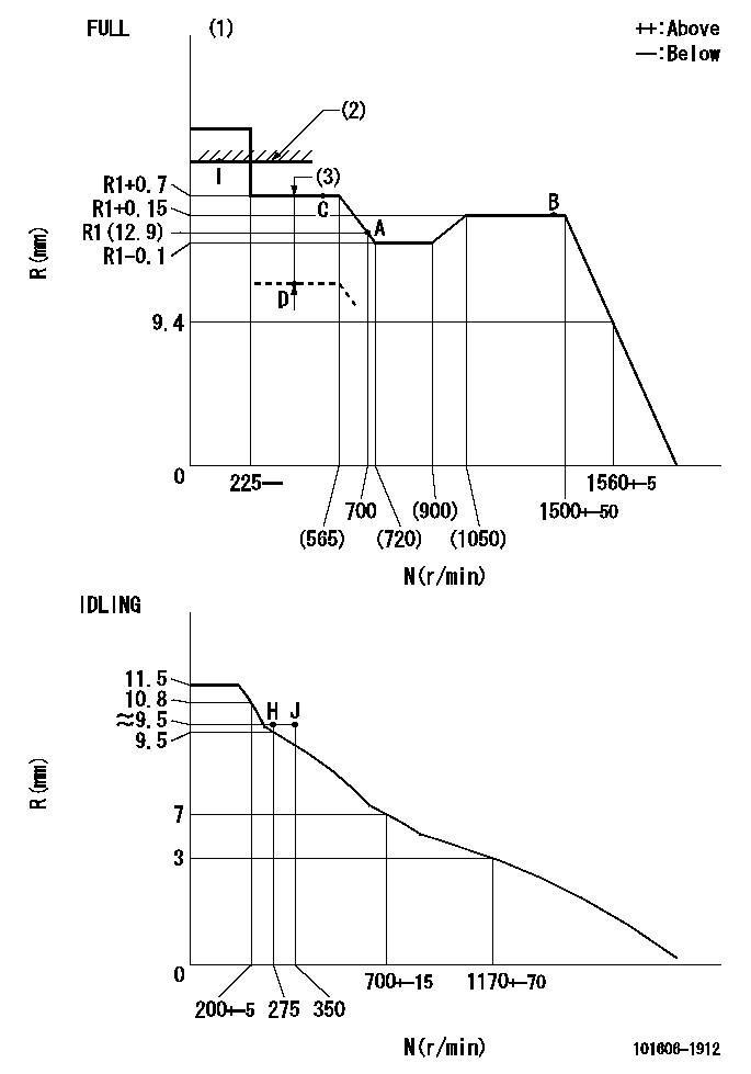
N:Pump speed
R:Rack position (mm)
(1)Torque cam stamping: T1
(2)RACK LIMIT
(3)Boost compensator stroke: BCL
----------
T1=E33 BCL=1.5+-0.1mm
----------
----------
T1=E33 BCL=1.5+-0.1mm
----------
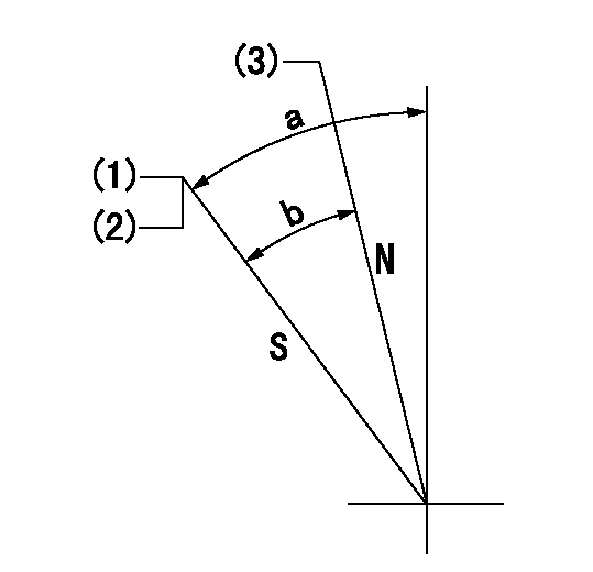
Speed control lever angle

F:Full speed
I:Idle
(1)Use the hole at R = aa
(2)Stopper bolt set position 'H'
----------
aa=29mm
----------
a=10deg+-5deg b=47deg+-3deg
----------
aa=29mm
----------
a=10deg+-5deg b=47deg+-3deg
Stop lever angle
N:Pump normal
S:Stop the pump.
(1)Set the stopper bolt at pump speed = aa and rack position = bb (non-injection rack position). Confirm non-injection.
(2)After setting the stopper bolt, confirm non-injection at speed cc. Rack position = dd (non-injection rack position).
(3)Rack position = approximately ee.
----------
aa=1350r/min bb=6.5-0.5mm cc=275r/min dd=(8.5)mm ee=17.4mm
----------
a=38.5deg+-5deg b=19deg+-5deg
----------
aa=1350r/min bb=6.5-0.5mm cc=275r/min dd=(8.5)mm ee=17.4mm
----------
a=38.5deg+-5deg b=19deg+-5deg
0000001501 MICRO SWITCH
Adjustment of the micro-switch
Adjust the bolt to obtain the following lever position when the micro-switch is ON.
(1)Speed N1
(2)Rack position Ra
----------
N1=400+-5r/min Ra=9.2mm
----------
----------
N1=400+-5r/min Ra=9.2mm
----------
Timing setting

(1)Pump vertical direction
(2)Position of timer's tooth at No 1 cylinder's beginning of injection
(3)B.T.D.C.: aa
(4)-
----------
aa=11deg
----------
a=(1deg)
----------
aa=11deg
----------
a=(1deg)
Information:
Adjust - to conform and correspond to specifications. Check - to observe for satisfactory conditions, accuracy, safety or performance. Exchange - to trade a worn or failing component for a remanufactured or rebuilt component. Inspect - to examine closely, in critical appraisal, while testing or evaluating components or systems. Inspect/Rebuild or Exchange - to examine closely, then making the decision on repair option (i.e. Rebuild or Exchange). Lubricate - to apply a lubricant (oil, grease, etc.) as specified for reducing friction, heat and wear between solid surfaces. Protective Devices - indicators such as gauges, lights, emergency shutoffs, etc., that alert an operator that a potential problem may exist. Failure to respond to these indicators in a timely manner could result in serious engine damage. Rebuild - to repair worn or failing component with new parts, components and/or remanufactured components. Replace - to install something new, remanufactured or rebuilt in place of an existing worn or failing component. Service Hours (Electrical) - records the time (clock hours) the engine is actually running but does not reflect variations in speed, load, etc. Some engines are equipped with mechanical service meters reading in Service Meter Units (SMU). The Maintenance Schedules are developed for clock hours or fuel consumption. For most users, clock hours are the standard interval for maintenance and SMU's can be roughly equal to clock hours. However, Caterpillar recommends that fuel consumption be used as the preferred method of determining intervals rather than SMU's or clock hours.Interval Categories
Engine components can generally be grouped into speed sensitive and load sensitive categories. The maintenance interval for each item listed in the Maintenance Schedule is based on either engine speed or load. Speed sensitive items such as water pumps an air compressors are not primarily affected by the operating load on your engine. The load on an engine will not significantly accelerate the repair or replacement cycle for speed sensitive items. The maintenance intervals established for speed sensitive items are based on service hours. Load sensitive items such as piston rings and cylinder liners are affected by the operating load on your engine. Generally speaking, the lower the load, the longer the engine life. Conversely, the higher the load, the shorter the engine life. A heavy load on an engine will accelerate the repair or replacement cycle for load sensitive items.Load sensitive items are normally internal engine components. The amount of fuel consumed is directly related to the load on your engine.The maintenance interval for load sensitive items includes fuel consumption, since the amount of fuel consumed is directly related to the load on your engine.Caterpillar recommends performing maintenance on load sensitive items at maintenance intervals based on the quantity of fuel consumed.
Engine components can generally be grouped into speed sensitive and load sensitive categories. The maintenance interval for each item listed in the Maintenance Schedule is based on either engine speed or load. Speed sensitive items such as water pumps an air compressors are not primarily affected by the operating load on your engine. The load on an engine will not significantly accelerate the repair or replacement cycle for speed sensitive items. The maintenance intervals established for speed sensitive items are based on service hours. Load sensitive items such as piston rings and cylinder liners are affected by the operating load on your engine. Generally speaking, the lower the load, the longer the engine life. Conversely, the higher the load, the shorter the engine life. A heavy load on an engine will accelerate the repair or replacement cycle for load sensitive items.Load sensitive items are normally internal engine components. The amount of fuel consumed is directly related to the load on your engine.The maintenance interval for load sensitive items includes fuel consumption, since the amount of fuel consumed is directly related to the load on your engine.Caterpillar recommends performing maintenance on load sensitive items at maintenance intervals based on the quantity of fuel consumed.
Have questions with 101606-1912?
Group cross 101606-1912 ZEXEL
Mitsubishi
101606-1912
9 400 615 476
ME076284
INJECTION-PUMP ASSEMBLY
6D15T2
6D15T2