Information injection-pump assembly
BOSCH
9 400 615 470
9400615470
ZEXEL
101606-1850
1016061850
MITSUBISHI
ME076233
me076233
Rating:
Include in #1:
101401-7330
as _
Cross reference number
BOSCH
9 400 615 470
9400615470
ZEXEL
101606-1850
1016061850
MITSUBISHI
ME076233
me076233
Zexel num
Bosch num
Firm num
Name
Calibration Data:
Adjustment conditions
Test oil
1404 Test oil ISO4113 or {SAEJ967d}
1404 Test oil ISO4113 or {SAEJ967d}
Test oil temperature
degC
40
40
45
Nozzle and nozzle holder
105780-8140
Bosch type code
EF8511/9A
Nozzle
105780-0000
Bosch type code
DN12SD12T
Nozzle holder
105780-2080
Bosch type code
EF8511/9
Opening pressure
MPa
17.2
Opening pressure
kgf/cm2
175
Injection pipe
Outer diameter - inner diameter - length (mm) mm 6-2-600
Outer diameter - inner diameter - length (mm) mm 6-2-600
Overflow valve
131424-5520
Overflow valve opening pressure
kPa
255
221
289
Overflow valve opening pressure
kgf/cm2
2.6
2.25
2.95
Tester oil delivery pressure
kPa
157
157
157
Tester oil delivery pressure
kgf/cm2
1.6
1.6
1.6
Direction of rotation (viewed from drive side)
Left L
Left L
Injection timing adjustment
Direction of rotation (viewed from drive side)
Left L
Left L
Injection order
1-5-3-6-
2-4
Pre-stroke
mm
3.5
3.45
3.55
Beginning of injection position
Governor side NO.1
Governor side NO.1
Difference between angles 1
Cal 1-5 deg. 60 59.5 60.5
Cal 1-5 deg. 60 59.5 60.5
Difference between angles 2
Cal 1-3 deg. 120 119.5 120.5
Cal 1-3 deg. 120 119.5 120.5
Difference between angles 3
Cal 1-6 deg. 180 179.5 180.5
Cal 1-6 deg. 180 179.5 180.5
Difference between angles 4
Cyl.1-2 deg. 240 239.5 240.5
Cyl.1-2 deg. 240 239.5 240.5
Difference between angles 5
Cal 1-4 deg. 300 299.5 300.5
Cal 1-4 deg. 300 299.5 300.5
Injection quantity adjustment
Adjusting point
-
Rack position
11.1
Pump speed
r/min
900
900
900
Each cylinder's injection qty
mm3/st.
71.9
69.7
74.1
Basic
*
Fixing the rack
*
Standard for adjustment of the maximum variation between cylinders
*
Injection quantity adjustment_02
Adjusting point
H
Rack position
9.5+-0.5
Pump speed
r/min
275
275
275
Each cylinder's injection qty
mm3/st.
8.7
8.2
9.2
Fixing the rack
*
Standard for adjustment of the maximum variation between cylinders
*
Injection quantity adjustment_03
Adjusting point
A
Rack position
R1(11.1)
Pump speed
r/min
900
900
900
Average injection quantity
mm3/st.
71.9
70.9
72.9
Basic
*
Fixing the lever
*
Injection quantity adjustment_04
Adjusting point
B
Rack position
R1+0.2
Pump speed
r/min
1400
1400
1400
Average injection quantity
mm3/st.
81.7
77.7
85.7
Fixing the lever
*
Injection quantity adjustment_05
Adjusting point
C
Rack position
R1+0.1
Pump speed
r/min
550
550
550
Average injection quantity
mm3/st.
51.8
47.8
55.8
Fixing the lever
*
Injection quantity adjustment_06
Adjusting point
I
Rack position
-
Pump speed
r/min
100
100
100
Average injection quantity
mm3/st.
85
65
105
Fixing the lever
*
Rack limit
*
Timer adjustment
Pump speed
r/min
1150
Advance angle
deg.
0.5
Timer adjustment_02
Pump speed
r/min
1250
Advance angle
deg.
2.5
2
3
Timer adjustment_03
Pump speed
r/min
1350
Advance angle
deg.
5
4.5
5.5
Remarks
Finish
Finish
Test data Ex:
Governor adjustment
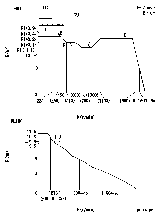
N:Pump speed
R:Rack position (mm)
(1)Torque cam stamping: T1
(2)RACK LIMIT
----------
T1=D15
----------
----------
T1=D15
----------
Speed control lever angle

F:Full speed
I:Idle
(1)Use the hole at R = aa
(2)Stopper bolt set position 'H'
----------
aa=29mm
----------
a=10deg+-5deg b=(46deg)+-3deg
----------
aa=29mm
----------
a=10deg+-5deg b=(46deg)+-3deg
Stop lever angle
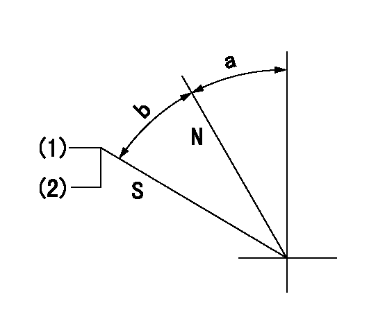
N:Pump normal
S:Stop the pump.
(1)Set the stopper bolt at speed = rated point and rack position = aa (non-injection rack position). Confirm non-injection.
(2)After setting the stopper bolt , confirm non-injection at pump speed bb. Rack position = cc (non-injection rack position).
----------
aa=(6.5)mm bb=275r/min cc=(6.5)mm
----------
a=11.5deg+-5deg b=(27deg)+-5deg
----------
aa=(6.5)mm bb=275r/min cc=(6.5)mm
----------
a=11.5deg+-5deg b=(27deg)+-5deg
0000001501 MICRO SWITCH
Adjustment of the micro-switch
Adjust the bolt to obtain the following lever position when the micro-switch is ON.
(1)Speed N1
(2)Rack position Ra
----------
N1=400+-5r/min Ra=9.2mm
----------
----------
N1=400+-5r/min Ra=9.2mm
----------
Timing setting

(1)Pump vertical direction
(2)Position of timer's tooth at No 1 cylinder's beginning of injection
(3)B.T.D.C.: aa
(4)-
----------
aa=12deg
----------
a=(1deg)
----------
aa=12deg
----------
a=(1deg)
Information:
Fuel Recommendations
Fill the fuel tank at the end of each day of operation to drive out moist air and prevent condensation. Maintain a fairly consistent level in the day tank (near the top) to avoid drawing moisture into the tank as the level decreases.Do not fill the tank to the top. Fuel expands as it warms, and may overflow.Do not fill fuel filters with fuel before installing them. Contaminated fuel causes accelerated wear to fuel system parts.
Use fuel only as recommended in this section. Fuel grades recommended for use in Caterpillar diesel engines are: No.2-D diesel fuel with low sulfur (0.05 percent maximum), or regular sulfur (0.5 percent maximum). No. 1 grades are acceptable.The following chart lists worldwide fuel standards which meet Caterpillar requirements. Aviation kerosene-type fuels meeting acceptable limits may also be used as an engine fuel. The following chart lists some of the acceptable kerosene-type fuels. Fuel viscosity is a major concern with aviation fuels. A minimum viscosity of 1.4 cSt at 38°C (100°F) is required to properly lubricate Caterpillar fuel system components. These kerosene-type fuels have a lower viscosity for low temperature operation.The kerosene-type fuels have less energy per unit volume than diesel fuels, producing less peak power. More kerosene-type fuel is needed than diesel fuel to do the same amount of work.Caterpillar Diesel Engines are capable of burning a wide range of distillate fuels. Burning clean, stable blends of distillate fuel meeting the following requirements will provide quality engine service life. When economics or fuel availability dictate, other fuel types may be burned in the engine. Consult your Caterpillar dealer for more information and advice on any specific fuel.Cetane Number
Under average starting conditions, direct injection engines require a minimum cetane number of 40. A higher cetane value may be required for high altitude or cold weather operation.Filterability
Clean fuels should have no more than 0.1 percent of sediment and water. Fuel stored for extended periods of time may oxidize and form solids, causing filtering problems.Pour Point
Fuel pour point should be at least 6°C (10°F) below the lowest ambient temperature at which the engines must start and operate. Lower pour points of No.1 or No.1-D fuel may be necessary in extremely cold weather.Cloud Point
The cloud point should be below the lowest ambient temperature at which the engines must start and operate, to prevent the fuel filter elements from plugging with wax crystals. Refer to Fuel Problems in Cold Weather Operation for additional information.Viscosity
Fluid viscosity is a measure of resistance to flow. Fuel viscosity is important because it effects lubrication of fuel system components, and fuel atomization. The provided viscosity limits address both of those effects.Additives
Fuel additives are generally not recommended or needed for the specified fuels listed. Acetone improvers can be used as necessary for direct injection engine requirements. Biocides may be needed to eliminate microorganism growth in storage tanks. In cold conditions, treatment for entrained water may also be necessary.Consult your fuel supplier about the use of additives to prevent incompatibility among additives already in