Information injection-pump assembly
BOSCH
9 400 615 469
9400615469
ZEXEL
101606-1840
1016061840
MITSUBISHI
ME076221
me076221

Rating:
Include in #1:
101401-7320
as _
Cross reference number
BOSCH
9 400 615 469
9400615469
ZEXEL
101606-1840
1016061840
MITSUBISHI
ME076221
me076221
Zexel num
Bosch num
Firm num
Name
Calibration Data:
Adjustment conditions
Test oil
1404 Test oil ISO4113 or {SAEJ967d}
1404 Test oil ISO4113 or {SAEJ967d}
Test oil temperature
degC
40
40
45
Nozzle and nozzle holder
105780-8140
Bosch type code
EF8511/9A
Nozzle
105780-0000
Bosch type code
DN12SD12T
Nozzle holder
105780-2080
Bosch type code
EF8511/9
Opening pressure
MPa
17.2
Opening pressure
kgf/cm2
175
Injection pipe
Outer diameter - inner diameter - length (mm) mm 6-2-600
Outer diameter - inner diameter - length (mm) mm 6-2-600
Overflow valve
131424-5520
Overflow valve opening pressure
kPa
255
221
289
Overflow valve opening pressure
kgf/cm2
2.6
2.25
2.95
Tester oil delivery pressure
kPa
157
157
157
Tester oil delivery pressure
kgf/cm2
1.6
1.6
1.6
Direction of rotation (viewed from drive side)
Left L
Left L
Injection timing adjustment
Direction of rotation (viewed from drive side)
Left L
Left L
Injection order
1-5-3-6-
2-4
Pre-stroke
mm
3.3
3.25
3.35
Beginning of injection position
Governor side NO.1
Governor side NO.1
Difference between angles 1
Cal 1-5 deg. 60 59.5 60.5
Cal 1-5 deg. 60 59.5 60.5
Difference between angles 2
Cal 1-3 deg. 120 119.5 120.5
Cal 1-3 deg. 120 119.5 120.5
Difference between angles 3
Cal 1-6 deg. 180 179.5 180.5
Cal 1-6 deg. 180 179.5 180.5
Difference between angles 4
Cyl.1-2 deg. 240 239.5 240.5
Cyl.1-2 deg. 240 239.5 240.5
Difference between angles 5
Cal 1-4 deg. 300 299.5 300.5
Cal 1-4 deg. 300 299.5 300.5
Injection quantity adjustment
Adjusting point
-
Rack position
10.4
Pump speed
r/min
850
850
850
Each cylinder's injection qty
mm3/st.
55.2
53.5
56.9
Basic
*
Fixing the rack
*
Standard for adjustment of the maximum variation between cylinders
*
Injection quantity adjustment_02
Adjusting point
H
Rack position
9.5+-0.5
Pump speed
r/min
275
275
275
Each cylinder's injection qty
mm3/st.
10.5
9
12
Fixing the rack
*
Standard for adjustment of the maximum variation between cylinders
*
Injection quantity adjustment_03
Adjusting point
A
Rack position
R1(10.4)
Pump speed
r/min
850
850
850
Average injection quantity
mm3/st.
55.2
54.2
56.2
Basic
*
Fixing the lever
*
Injection quantity adjustment_04
Adjusting point
B
Rack position
R1(10.4)
Pump speed
r/min
1450
1450
1450
Average injection quantity
mm3/st.
64.3
60.3
68.3
Fixing the lever
*
Injection quantity adjustment_05
Adjusting point
C
Rack position
R1+0.4
Pump speed
r/min
600
600
600
Average injection quantity
mm3/st.
50.7
46.7
54.7
Fixing the lever
*
Injection quantity adjustment_06
Adjusting point
I
Rack position
-
Pump speed
r/min
100
100
100
Average injection quantity
mm3/st.
90
70
110
Fixing the lever
*
Injection quantity adjustment_07
Adjusting point
D
Rack position
(R1+0.8)
Pump speed
r/min
500
500
500
Average injection quantity
mm3/st.
56.4
52.4
60.4
Fixing the lever
*
Rack limit
*
Timer adjustment
Pump speed
r/min
1250--
Advance angle
deg.
0
0
0
Remarks
Start
Start
Timer adjustment_02
Pump speed
r/min
1200
Advance angle
deg.
0.5
Timer adjustment_03
Pump speed
r/min
1400
Advance angle
deg.
5
4.5
5.5
Remarks
Finish
Finish
Test data Ex:
Governor adjustment
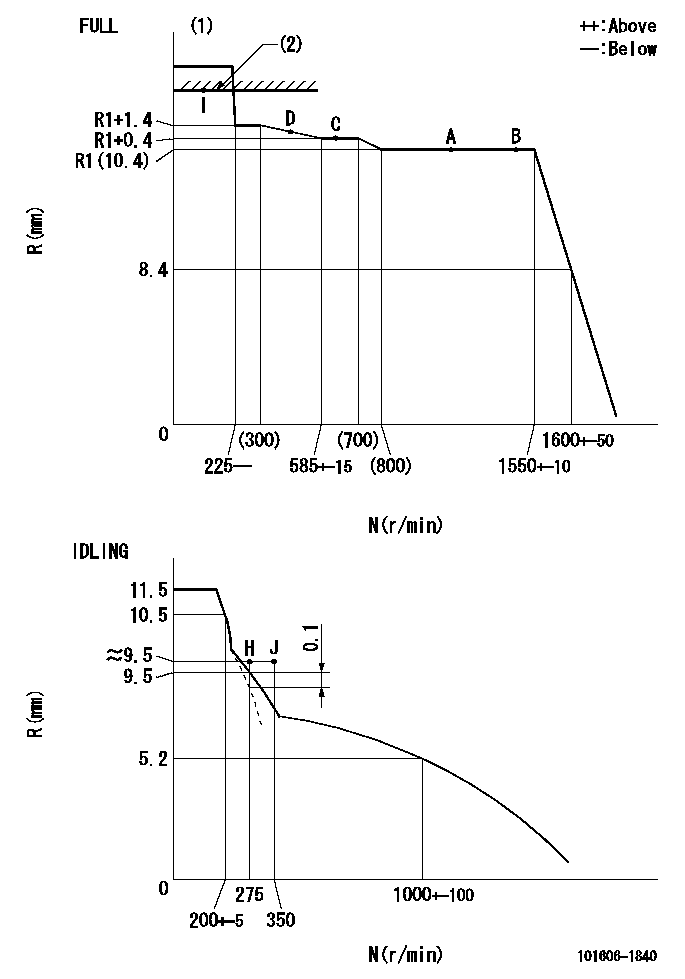
N:Pump speed
R:Rack position (mm)
(1)Torque cam stamping: T1
(2)RACK LIMIT
----------
T1=D25
----------
----------
T1=D25
----------
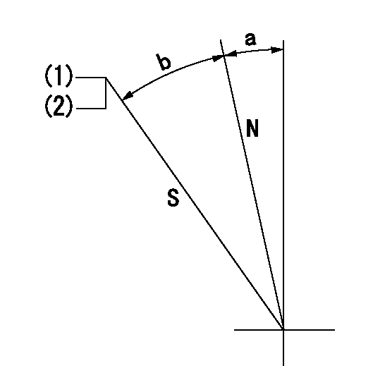
Speed control lever angle

F:Full speed
I:Idle
(1)Stopper bolt set position 'H'
----------
----------
a=10deg+-5deg b=(46deg)+-3deg
----------
----------
a=10deg+-5deg b=(46deg)+-3deg
Stop lever angle
N:Pump normal
S:Stop the pump.
(1)Set the stopper bolt at pump speed = aa and rack position = bb (non-injection rack position). Confirm non-injection.
(2)After setting the stopper bolt, confirm non-injection at speed cc. Rack position = dd (non-injection rack position).
----------
aa=1550r/min bb=6.4-0.5mm cc=275r/min dd=6.4-0.5mm
----------
a=11.5deg+-5deg b=24.5deg+-5deg
----------
aa=1550r/min bb=6.4-0.5mm cc=275r/min dd=6.4-0.5mm
----------
a=11.5deg+-5deg b=24.5deg+-5deg
0000001501 MICRO SWITCH
Adjustment of the micro-switch
Adjust the bolt to obtain the following lever position when the micro-switch is ON.
(1)Speed N1
(2)Rack position Ra
----------
N1=400+-5r/min Ra=9.2mm
----------
----------
N1=400+-5r/min Ra=9.2mm
----------
Timing setting

(1)Pump vertical direction
(2)Position of timer's tooth at No 1 cylinder's beginning of injection
(3)B.T.D.C.: aa
(4)-
----------
aa=14deg
----------
a=(0deg)
----------
aa=14deg
----------
a=(0deg)
Information:
Supplemental Coolant Additive (SCA)
Supplemental cooling system additive contains alkali. To prevent personal injury, do not drink, avoid contact with the skin and eyes.
The cooling system MUST contain supplemental coolant additive (SCA) for proper engine protection, regardless of antifreeze concentration.
DO NOT mix Caterpillar SCA or coolant additive elements with another manufacturer's products: select a cooling system treatment and use it exclusively.
SCA is necessary for proper conventional coolant maintenance. Most coolants DO NOT contain sufficient SCA for diesel engine application.
Do not exceed the recommended six percent SCA concentration. Excessive SCA concentration can form deposits on the higher temperature surfaces of the cooling system, reducing the engine's heat transfer characteristics. Reduced heat transfer could cause cracking of the cylinder head and other high temperature components. Excessive SCA concentration could also result in radiator tube blockage, overheating, and/or accelerated water pump seal wear. Never use both liquid SCA and the spin-on element (if equipped) at the same time. The use of those additives together could result in SCA concentration exceeding the recommended six percent maximum.
Use liquid SCA or a SCA element (if equipped) to maintain a three to six percent SCA concentration in the coolant. Caterpillar Test Kits check for concentration of nitrites in the coolant solution. Some manufacturers' SCA are phosphate based. Caterpillar Test Kits provide inaccurate results with phosphate based SCA. Commercial SCA products must contain silicates and a minimum of 70 grams per 3.8 L (1 US gal) (1200 ppm) nitrites. If another manufacturer's SCA is used, use that manufacturer's test kit. Follow the manufacturer's recommendations for cooling system treatment and test evaluation.Test the coolant periodically to monitor SCA levels. Use the 4C9301 Test Kit to check for Caterpillar SCA concentration. The Kit also provides cooling system maintenance recommendations. This kit is specifically for use with Caterpillar SCA's. The 8T5296 Test Kit can also to check for Caterpillar SCA concentration.The following charts lists the part numbers and quantities of SCA (liquid and solid) available from your Caterpillar dealer. Follow the instructions on the label. Permitted-Water/SCA Coolant
Never use water alone without SCA or inhibited coolant. Water alone is corrosive at engine operating temperatures.
A mixture of water and SCA does not protect against freezing or boiling.
A coolant mixture of water and SCA will cool and provide some protection to engine components, but it will NOT provide normal engine service life.
Caterpillar's recommendation for proper coolant is a minimum concentration of 30 percent glycol and 70 percent Acceptable water and SCA (3 percent of the total mixture). This recommendation will maintain cooling system corrosion protection.
In applications where freeze protection is not required, or where antifreeze is not available, a coolant mixture of Acceptable water and SCA can be used. A Water/SCA system should maintain a six to eight percent SCA concentration. DO NOT exceed eight percent maximum SCA concentration. SCA concentration levels must be monitored.The 8T5296 Test Kit can be used to evaluate the SCA concentration in Water/SCA coolant, with the following modifications to label instruction Step 3 and Step 5.STEP 3. Add