Information injection-pump assembly
ZEXEL
101606-1751
1016061751
MITSUBISHI
ME035492
me035492

Rating:
Service parts 101606-1751 INJECTION-PUMP ASSEMBLY:
1.
_
6.
COUPLING PLATE
7.
COUPLING PLATE
8.
_
9.
_
11.
Nozzle and Holder
ME035748
12.
Open Pre:MPa(Kqf/cm2)
21.6(220)
13.
NOZZLE-HOLDER

15.
NOZZLE SET
Include in #1:
101606-1751
as INJECTION-PUMP ASSEMBLY
Include in #2:
104746-6272
as _
Cross reference number
ZEXEL
101606-1751
1016061751
MITSUBISHI
ME035492
me035492
Zexel num
Bosch num
Firm num
Name
101606-1751
ME035492 MITSUBISHI
INJECTION-PUMP ASSEMBLY
6D15 * K
6D15 * K
Calibration Data:
Adjustment conditions
Test oil
1404 Test oil ISO4113 or {SAEJ967d}
1404 Test oil ISO4113 or {SAEJ967d}
Test oil temperature
degC
40
40
45
Nozzle and nozzle holder
105780-8140
Bosch type code
EF8511/9A
Nozzle
105780-0000
Bosch type code
DN12SD12T
Nozzle holder
105780-2080
Bosch type code
EF8511/9
Opening pressure
MPa
17.2
Opening pressure
kgf/cm2
175
Injection pipe
Outer diameter - inner diameter - length (mm) mm 6-2-600
Outer diameter - inner diameter - length (mm) mm 6-2-600
Overflow valve
131424-5520
Overflow valve opening pressure
kPa
255
221
289
Overflow valve opening pressure
kgf/cm2
2.6
2.25
2.95
Tester oil delivery pressure
kPa
157
157
157
Tester oil delivery pressure
kgf/cm2
1.6
1.6
1.6
Direction of rotation (viewed from drive side)
Left L
Left L
Injection timing adjustment
Direction of rotation (viewed from drive side)
Left L
Left L
Injection order
1-5-3-6-
2-4
Pre-stroke
mm
3.6
3.55
3.65
Beginning of injection position
Governor side NO.1
Governor side NO.1
Difference between angles 1
Cal 1-5 deg. 60 59.5 60.5
Cal 1-5 deg. 60 59.5 60.5
Difference between angles 2
Cal 1-3 deg. 120 119.5 120.5
Cal 1-3 deg. 120 119.5 120.5
Difference between angles 3
Cal 1-6 deg. 180 179.5 180.5
Cal 1-6 deg. 180 179.5 180.5
Difference between angles 4
Cyl.1-2 deg. 240 239.5 240.5
Cyl.1-2 deg. 240 239.5 240.5
Difference between angles 5
Cal 1-4 deg. 300 299.5 300.5
Cal 1-4 deg. 300 299.5 300.5
Injection quantity adjustment
Adjusting point
-
Rack position
11.1
Pump speed
r/min
850
850
850
Each cylinder's injection qty
mm3/st.
69
66.9
71.1
Basic
*
Fixing the rack
*
Standard for adjustment of the maximum variation between cylinders
*
Injection quantity adjustment_02
Adjusting point
H
Rack position
9.9+-0.5
Pump speed
r/min
275
275
275
Each cylinder's injection qty
mm3/st.
9.2
8.1
10.3
Fixing the rack
*
Standard for adjustment of the maximum variation between cylinders
*
Injection quantity adjustment_03
Adjusting point
A
Rack position
R1(11.1)
Pump speed
r/min
850
850
850
Average injection quantity
mm3/st.
69
68
70
Basic
*
Fixing the lever
*
Injection quantity adjustment_04
Adjusting point
B
Rack position
R1+0.35
Pump speed
r/min
1450
1450
1450
Average injection quantity
mm3/st.
82.5
78.5
86.5
Fixing the lever
*
Injection quantity adjustment_05
Adjusting point
C
Rack position
R1-0.2
Pump speed
r/min
600
600
600
Average injection quantity
mm3/st.
47.6
43.6
51.6
Fixing the lever
*
Injection quantity adjustment_06
Adjusting point
I
Rack position
-
Pump speed
r/min
100
100
100
Average injection quantity
mm3/st.
80
75
85
Fixing the lever
*
Rack limit
*
Timer adjustment
Pump speed
r/min
1250--
Advance angle
deg.
0
0
0
Remarks
Start
Start
Timer adjustment_02
Pump speed
r/min
1200
Advance angle
deg.
0.5
Timer adjustment_03
Pump speed
r/min
1350
Advance angle
deg.
2.4
1.9
2.9
Timer adjustment_04
Pump speed
r/min
1500
Advance angle
deg.
5
4.5
5.5
Remarks
Finish
Finish
Test data Ex:
Governor adjustment
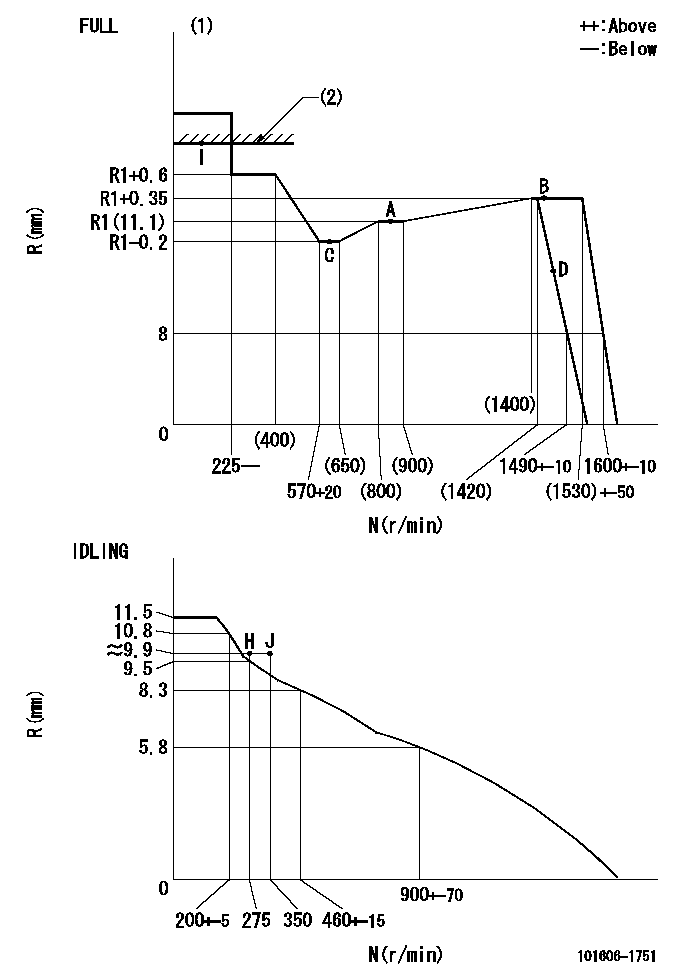
N:Pump speed
R:Rack position (mm)
(1)Torque cam stamping: T1
(2)RACK LIMIT
----------
T1=C98
----------
----------
T1=C98
----------
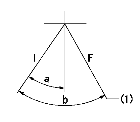
Speed control lever angle

F:Full speed
I:Idle
(1)Stopper bolt set position 'H'
----------
----------
a=10deg+-5deg b=(46deg)+-3deg
----------
----------
a=10deg+-5deg b=(46deg)+-3deg
Stop lever angle

N:Engine manufacturer's normal use
S:Stop the pump.
(1)Set the stopper bolt at pump speed = aa and rack position = bb (non-injection rack position). Confirm non-injection.
(2)After setting the stopper bolt, confirm non-injection at speed cc. Rack position = dd (non-injection rack position).
(3)Rack position = approximately ee.
(4)Free (at shipping)
----------
aa=1450r/min bb=(7.1)mm cc=275r/min dd=(8.8)mm ee=17.4mm
----------
a=38.5deg+-5deg b=(27deg) c=17deg+-5deg
----------
aa=1450r/min bb=(7.1)mm cc=275r/min dd=(8.8)mm ee=17.4mm
----------
a=38.5deg+-5deg b=(27deg) c=17deg+-5deg
0000001201
I:Idle
F:At operation, hold it in the full speed position.
(1)Rack position = aa, speed = bb.
----------
aa=8mm bb=1490r/min
----------
a=15deg+-5deg b=(43deg)+-3deg
----------
aa=8mm bb=1490r/min
----------
a=15deg+-5deg b=(43deg)+-3deg
0000001501 MICRO SWITCH
Adjustment of the micro-switch
Adjust the bolt to obtain the following lever position when the micro-switch is ON.
(1)Speed N1
(2)Rack position Ra
----------
N1=400+-5r/min Ra=9.7mm
----------
----------
N1=400+-5r/min Ra=9.7mm
----------
Timing setting

(1)Pump vertical direction
(2)Position of timer's tooth at No 1 cylinder's beginning of injection
(3)B.T.D.C.: aa
(4)-
----------
aa=12deg
----------
a=(1deg)
----------
aa=12deg
----------
a=(1deg)
Information:
Caterpillar Reference Material
The following literature can be obtained through any Caterpillar dealer.Oil
SEBD0640, Oil and Your EnginePEDP7122, Question & Answer BookletPEDP1129, Listen To Your OilPEHP6001, How to Take a Good Oil SampleSEBU6251, Lubricant RecommendationsPEHP1027, Product Data Sheet for Cat Diesel Engine Oil (CD)PEHP0002, Product Data Sheet for Cat Molybdenum Grease (MPGM)PEHP0003, Product Data Sheet for Cat Lithium Grease (MPGL)PEHP0017, Product Data Sheet for Cat Special Purpose Grease (SPG)PEWP9733, Cat Fluids SelectorPEDP7105, Scheduled Oil SamplingFuel
SEBD0717, Diesel Fuels and Your EngineCoolant
SEBD0518, Know Your Cooling SystemSEBD0970, Coolant and Your EngineMiscellaneous
SEBF8029, Index to Guidelines for Reusable Parts and Salvage OperationsSEBF8062, Guideline for Reusable Parts - Cleaning and Inspection of Air FiltersSEHS9031, Storage Procedure for Caterpillar ProductsSENR5226, Service Manual (EMCP)SEBU6150, SR4 Generators and Control Panels Operation and Maintenance ManualSEBU6918, SR4B Generators and Control Panels Operation and Maintenance ManualSENR7337, Service Manual, 3408 and 3408B Industrial and Marine EnginesSENR7405, Service Manual, 3412 Industrial and Marine EnginesSENR2559, Service Manual, 3408 and 3412 Generator Set EnginesSEHS7654, Alignment-General InstructionsSEHS9124, Cleaning and Drying of Caterpillar Electric Set GeneratorsLEBH9324, Agricultural and Material Handling Application and Installation GuideSEHS7292, Use of 5P4150 Nozzle Testing GroupSEHS8622, Using the FT1984 Air-To-Air Aftercooler Leak Test GroupSEHS7795, Use of Pump & Governor Tool GroupSEHS8024, Governor Adjusting Tool GroupSEHS8094, Use of Nozzle Puller GroupAdditional Reference Material
ASTM D2896- TBN MeasurementsASTM D21768- Worked PenetrationASTM D2982B- Ethylene Glycol ContentASTM D3828A- Fuel DilutionASTM D445- ViscosityASTM D893- InsolublesASTM 498589- GM-6038M SpecificationASTM Specs can normally be obtained from your local technological society, library or college.SAE J313- Diesel FuelsSAE J754- NomenclatureSAE J183- ClassificationSociety of Automotive Engineers (SAE) Specs can be found in your SAE handbook or can be obtained from your local library, college, or technological society.* SAE handbooks can be obtained directly from:SAE International
400 Commonwealth Drive
Warrendale, PA USA 15096-0001
Engine Manufacturers Association (EMA) information for lube oil selection can be obtained from your local library, college or technological society, or contact:* Engine Manufacturers AssociationLubricating Oils Data Book
401 N. Michigan Ave. Ste. 2400
Chicago, IL 60611
(312) 644-6610 ext. 3626
Have questions with 101606-1751?
Group cross 101606-1751 ZEXEL
Mitsubishi
101606-1751
ME035492
INJECTION-PUMP ASSEMBLY
6D15
6D15