Information injection-pump assembly
BOSCH
9 400 615 457
9400615457
ZEXEL
101606-1582
1016061582
MITSUBISHI
ME076223
me076223

Rating:
Include in #2:
104746-6241
as _
Cross reference number
BOSCH
9 400 615 457
9400615457
ZEXEL
101606-1582
1016061582
MITSUBISHI
ME076223
me076223
Zexel num
Bosch num
Firm num
Name
101606-1582
9 400 615 457
ME076223 MITSUBISHI
INJECTION-PUMP ASSEMBLY
6D14T K
6D14T K
Calibration Data:
Adjustment conditions
Test oil
1404 Test oil ISO4113 or {SAEJ967d}
1404 Test oil ISO4113 or {SAEJ967d}
Test oil temperature
degC
40
40
45
Nozzle and nozzle holder
105780-8140
Bosch type code
EF8511/9A
Nozzle
105780-0000
Bosch type code
DN12SD12T
Nozzle holder
105780-2080
Bosch type code
EF8511/9
Opening pressure
MPa
17.2
Opening pressure
kgf/cm2
175
Injection pipe
Outer diameter - inner diameter - length (mm) mm 6-2-600
Outer diameter - inner diameter - length (mm) mm 6-2-600
Overflow valve
131424-5520
Overflow valve opening pressure
kPa
255
221
289
Overflow valve opening pressure
kgf/cm2
2.6
2.25
2.95
Tester oil delivery pressure
kPa
157
157
157
Tester oil delivery pressure
kgf/cm2
1.6
1.6
1.6
Direction of rotation (viewed from drive side)
Left L
Left L
Injection timing adjustment
Direction of rotation (viewed from drive side)
Left L
Left L
Injection order
1-5-3-6-
2-4
Pre-stroke
mm
3.3
3.25
3.35
Beginning of injection position
Governor side NO.1
Governor side NO.1
Difference between angles 1
Cal 1-5 deg. 60 59.5 60.5
Cal 1-5 deg. 60 59.5 60.5
Difference between angles 2
Cal 1-3 deg. 120 119.5 120.5
Cal 1-3 deg. 120 119.5 120.5
Difference between angles 3
Cal 1-6 deg. 180 179.5 180.5
Cal 1-6 deg. 180 179.5 180.5
Difference between angles 4
Cyl.1-2 deg. 240 239.5 240.5
Cyl.1-2 deg. 240 239.5 240.5
Difference between angles 5
Cal 1-4 deg. 300 299.5 300.5
Cal 1-4 deg. 300 299.5 300.5
Injection quantity adjustment
Adjusting point
-
Rack position
12.7
Pump speed
r/min
800
800
800
Each cylinder's injection qty
mm3/st.
91.5
88.7
94.3
Basic
*
Fixing the rack
*
Standard for adjustment of the maximum variation between cylinders
*
Injection quantity adjustment_02
Adjusting point
H
Rack position
9.5+-0.5
Pump speed
r/min
275
275
275
Each cylinder's injection qty
mm3/st.
8
6.8
9.2
Fixing the rack
*
Standard for adjustment of the maximum variation between cylinders
*
Injection quantity adjustment_03
Adjusting point
A
Rack position
R1(12.7)
Pump speed
r/min
800
800
800
Average injection quantity
mm3/st.
91.5
90.5
92.5
Basic
*
Fixing the lever
*
Boost pressure
kPa
36.7
36.7
Boost pressure
mmHg
275
275
Injection quantity adjustment_04
Adjusting point
B
Rack position
R1-0.75
Pump speed
r/min
1450
1450
1450
Average injection quantity
mm3/st.
88.9
84.9
92.9
Fixing the lever
*
Boost pressure
kPa
36.7
36.7
Boost pressure
mmHg
275
275
Injection quantity adjustment_05
Adjusting point
C
Rack position
R1+0.2
Pump speed
r/min
600
600
600
Average injection quantity
mm3/st.
91.2
87.2
95.2
Fixing the lever
*
Boost pressure
kPa
36.7
36.7
Boost pressure
mmHg
275
275
Injection quantity adjustment_06
Adjusting point
D
Rack position
R2-0.9
Pump speed
r/min
300
300
300
Average injection quantity
mm3/st.
59.9
55.9
63.9
Fixing the lever
*
Boost pressure
kPa
0
0
0
Boost pressure
mmHg
0
0
0
Injection quantity adjustment_07
Adjusting point
I
Rack position
-
Pump speed
r/min
100
100
100
Average injection quantity
mm3/st.
99
79
119
Fixing the lever
*
Rack limit
*
Boost compensator adjustment
Pump speed
r/min
300
300
300
Rack position
R2-0.9
Boost pressure
kPa
7.3
7.3
7.3
Boost pressure
mmHg
55
55
55
Boost compensator adjustment_02
Pump speed
r/min
300
300
300
Rack position
R2-0.7
Boost pressure
kPa
10.7
9.4
12
Boost pressure
mmHg
80
70
90
Boost compensator adjustment_03
Pump speed
r/min
300
300
300
Rack position
R2(R1+0.
5)
Boost pressure
kPa
23.3
23.3
23.3
Boost pressure
mmHg
175
175
175
Timer adjustment
Pump speed
r/min
1200
Advance angle
deg.
0.5
Timer adjustment_02
Pump speed
r/min
1300
Advance angle
deg.
1.7
1.2
2.2
Timer adjustment_03
Pump speed
r/min
1400
Advance angle
deg.
3.5
3
4
Remarks
Finish
Finish
Test data Ex:
Governor adjustment
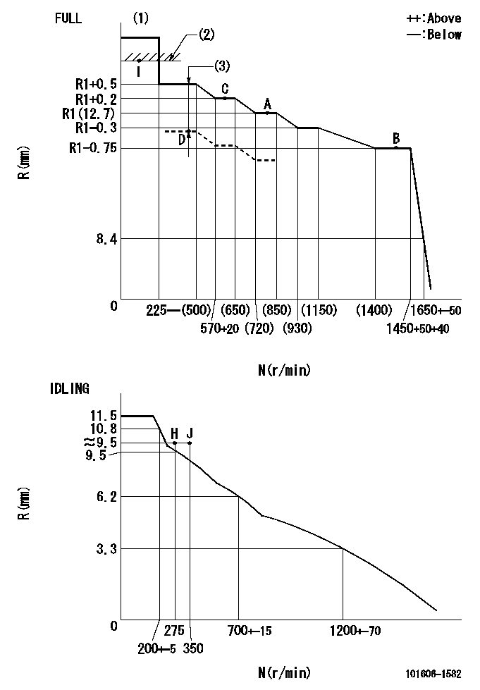
N:Pump speed
R:Rack position (mm)
(1)Torque cam stamping: T1
(2)RACK LIMIT
(3)Boost compensator stroke: BCL
----------
T1=D17 BCL=0.9+-0.1mm
----------
----------
T1=D17 BCL=0.9+-0.1mm
----------
Speed control lever angle

F:Full speed
I:Idle
(1)Stopper bolt set position 'H'
----------
----------
a=18.5deg+-5deg b=39deg+-3deg
----------
----------
a=18.5deg+-5deg b=39deg+-3deg
Stop lever angle
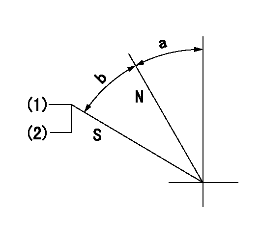
N:Pump normal
S:Stop the pump.
(1)Set the stopper bolt at speed = rated point and rack position = aa (non-injection rack position). Confirm non-injection.
(2)After setting the stopper bolt , confirm non-injection at pump speed bb. Rack position = cc (non-injection rack position).
----------
aa=6.5-0.5mm bb=275r/min cc=(8)mm
----------
a=11.5deg+-5deg b=27deg+-5deg
----------
aa=6.5-0.5mm bb=275r/min cc=(8)mm
----------
a=11.5deg+-5deg b=27deg+-5deg
0000001501 MICRO SWITCH
Adjustment of the micro-switch
Adjust the bolt to obtain the following lever position when the micro-switch is ON.
(1)Speed N1
(2)Rack position Ra
----------
N1=400+-5r/min Ra=9.2mm
----------
----------
N1=400+-5r/min Ra=9.2mm
----------
Timing setting

(1)Pump vertical direction
(2)Position of timer's tooth at No 1 cylinder's beginning of injection
(3)B.T.D.C.: aa
(4)-
----------
aa=12deg
----------
a=(1deg)
----------
aa=12deg
----------
a=(1deg)
Information:
Engine Lifting
When it is necessary to remove a component on an angle, remember that the capacity of an eyebolt is less as the angle between the supporting members and the object becomes less than 90 degrees. Eye Bolts and brackets should never be bent, and should only be loaded under tension.
Use a hoist to remove heavy components. Use an adjustable lifting beam to lift the engine. All supporting members (chains and cables) should be parallel to each other, and perpendicular as possible to the top of the object being lifted.Some removals require the use of lifting fixtures, to obtain proper balance and provide safe handling.To remove the engine ONLY, use the lifting eyes equipped with the engine.The lifting eyes are designed for the engine arrangement as sold. Modifying the lifting eyes and/or engine arrangement weight renders the lifting eyes and devices obsolete.If you modify the lifting eyes and/or engine arrangement weight, you are responsible for providing adequate lifting devices. Contact your Caterpillar dealer for information regarding fixtures for proper engine package lifting.Engine Lifting With Generator
Do not use the engine lifting eyes to remove the engine and generator together.
Lifting the engine and generator together requires special equipment and procedures. Contact your Caterpillar dealer for information regarding proper engine and fuel tank lifting.Engine Storage
The following Engine Storage procedures and recommendations minimize the possibility of damage to engines stored for one year or less.When an engine is not started for several weeks, the lubricating oil drains from the cylinder walls and piston rings. Rust can then form on the cylinder liner surface, increasing engine wear and decreasing engine life.Special precautions should be used with engines remaining out of service for extended periods.After one year, a complete protection procedure must be followed if the engine is kept in storage longer. To prevent excessive engine wear:* Be sure all lubrication recommendations mentioned in the Maintenance Schedule intervals chart are completed.* If freezing temperatures are expected, check the cooling system for adequate protection against freezing. A 50/50 solution of Caterpillar (permanent-type) Antifreeze and approved water will give protection to -29°C (-20°F).If it will be impossible to start the engine periodically, consult your Caterpillar dealer for instructions to prepare your engine for longer storage periods.Refer to Storage Procedures For Caterpillar Products, SEHS9031, for more detailed information on engine storage.Generator Storage Procedure
When a generator is stored, moisture may condense in the windings. Use a dry storage space and space heaters to minimize condensation. Refer to: Service Manual for SR4 Generators, SENR3985, or Special Instruction, SEHS9124, Cleaning and Drying of Caterpillar Electric Set Generators, or contact your Caterpillar dealer.After Storage
Test the main stator windings with a megohmmeter:* Before the initial startup of the generator set.* Every 3 months* if the generator is operating in a humid environment.* If the generator has not been run under load for 3 months* or more.*This is a guideline only. It may be necessary to megger more frequently if the environment is extremely humid or salty.
When servicing or repairing electric power generation
Have questions with 101606-1582?
Group cross 101606-1582 ZEXEL
Mitsubishi
101606-1582
9 400 615 457
ME076223
INJECTION-PUMP ASSEMBLY
6D14T
6D14T