Information injection-pump assembly
ZEXEL
101606-1580
1016061580
Rating:
Cross reference number
ZEXEL
101606-1580
1016061580
Zexel num
Bosch num
Firm num
Name
Calibration Data:
Adjustment conditions
Test oil
1404 Test oil ISO4113 or {SAEJ967d}
1404 Test oil ISO4113 or {SAEJ967d}
Test oil temperature
degC
40
40
45
Nozzle and nozzle holder
105780-8140
Bosch type code
EF8511/9A
Nozzle
105780-0000
Bosch type code
DN12SD12T
Nozzle holder
105780-2080
Bosch type code
EF8511/9
Opening pressure
MPa
17.2
Opening pressure
kgf/cm2
175
Injection pipe
Outer diameter - inner diameter - length (mm) mm 6-2-600
Outer diameter - inner diameter - length (mm) mm 6-2-600
Overflow valve
131424-5520
Overflow valve opening pressure
kPa
255
221
289
Overflow valve opening pressure
kgf/cm2
2.6
2.25
2.95
Tester oil delivery pressure
kPa
157
157
157
Tester oil delivery pressure
kgf/cm2
1.6
1.6
1.6
Direction of rotation (viewed from drive side)
Left L
Left L
Injection timing adjustment
Direction of rotation (viewed from drive side)
Left L
Left L
Injection order
1-5-3-6-
2-4
Pre-stroke
mm
3.3
3.25
3.35
Beginning of injection position
Governor side NO.1
Governor side NO.1
Difference between angles 1
Cal 1-5 deg. 60 59.5 60.5
Cal 1-5 deg. 60 59.5 60.5
Difference between angles 2
Cal 1-3 deg. 120 119.5 120.5
Cal 1-3 deg. 120 119.5 120.5
Difference between angles 3
Cal 1-6 deg. 180 179.5 180.5
Cal 1-6 deg. 180 179.5 180.5
Difference between angles 4
Cyl.1-2 deg. 240 239.5 240.5
Cyl.1-2 deg. 240 239.5 240.5
Difference between angles 5
Cal 1-4 deg. 300 299.5 300.5
Cal 1-4 deg. 300 299.5 300.5
Injection quantity adjustment
Adjusting point
-
Rack position
12.7
Pump speed
r/min
800
800
800
Each cylinder's injection qty
mm3/st.
91.5
88.7
94.3
Basic
*
Fixing the rack
*
Standard for adjustment of the maximum variation between cylinders
*
Injection quantity adjustment_02
Adjusting point
H
Rack position
9.5+-0.5
Pump speed
r/min
275
275
275
Each cylinder's injection qty
mm3/st.
8
6.8
9.2
Fixing the rack
*
Standard for adjustment of the maximum variation between cylinders
*
Injection quantity adjustment_03
Adjusting point
A
Rack position
R1(12.7)
Pump speed
r/min
800
800
800
Average injection quantity
mm3/st.
91.5
90.5
92.5
Basic
*
Fixing the lever
*
Boost pressure
kPa
36.7
36.7
Boost pressure
mmHg
275
275
Injection quantity adjustment_04
Adjusting point
B
Rack position
R1-0.85
Pump speed
r/min
1450
1450
1450
Average injection quantity
mm3/st.
85
81
89
Fixing the lever
*
Boost pressure
kPa
36.7
36.7
Boost pressure
mmHg
275
275
Injection quantity adjustment_05
Adjusting point
C
Rack position
R1+0.2
Pump speed
r/min
600
600
600
Average injection quantity
mm3/st.
91.2
87.2
95.2
Fixing the lever
*
Boost pressure
kPa
36.7
36.7
Boost pressure
mmHg
275
275
Injection quantity adjustment_06
Adjusting point
D
Rack position
R2-0.9
Pump speed
r/min
300
300
300
Average injection quantity
mm3/st.
59.9
55.9
63.9
Fixing the lever
*
Boost pressure
kPa
0
0
0
Boost pressure
mmHg
0
0
0
Injection quantity adjustment_07
Adjusting point
I
Rack position
-
Pump speed
r/min
100
100
100
Average injection quantity
mm3/st.
99
79
119
Fixing the lever
*
Rack limit
*
Boost compensator adjustment
Pump speed
r/min
300
300
300
Rack position
R2-0.9
Boost pressure
kPa
7.3
7.3
7.3
Boost pressure
mmHg
55
55
55
Boost compensator adjustment_02
Pump speed
r/min
300
300
300
Rack position
R2-0.7
Boost pressure
kPa
10.7
9.4
12
Boost pressure
mmHg
80
70
90
Boost compensator adjustment_03
Pump speed
r/min
300
300
300
Rack position
R2(R1+0.
5)
Boost pressure
kPa
23.3
23.3
23.3
Boost pressure
mmHg
175
175
175
Timer adjustment
Pump speed
r/min
1150++
Advance angle
deg.
0
0
0
Load
3/4
Remarks
Do not advance until starting N = 1150.
Do not advance until starting N = 1150.
Timer adjustment_02
Pump speed
r/min
1200
Advance angle
deg.
0.5
Load
4/4
Timer adjustment_03
Pump speed
r/min
1300
Advance angle
deg.
1.7
1.2
2.2
Load
4/4
Timer adjustment_04
Pump speed
r/min
1400
Advance angle
deg.
3.5
3
4
Load
4/4
Remarks
Finish
Finish
Test data Ex:
Governor adjustment
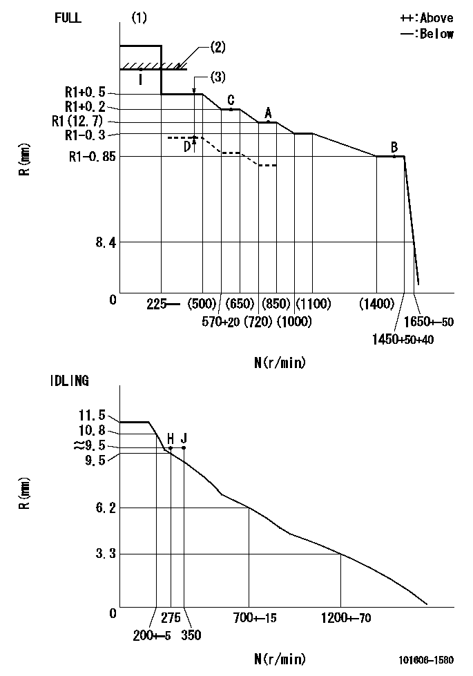
N:Pump speed
R:Rack position (mm)
(1)Torque cam stamping: T1
(2)RACK LIMIT
(3)Boost compensator stroke: BCL
----------
T1=C86 BCL=0.9+-0.1mm
----------
----------
T1=C86 BCL=0.9+-0.1mm
----------
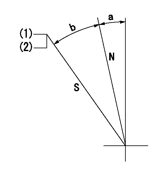
Speed control lever angle

F:Full speed
I:Idle
(1)Stopper bolt set position 'H'
----------
----------
a=18.5deg+-5deg b=39deg+-3deg
----------
----------
a=18.5deg+-5deg b=39deg+-3deg
Stop lever angle
N:Pump normal
S:Stop the pump.
(1)Set the stopper bolt at speed = rated point and rack position = aa (non-injection rack position). Confirm non-injection.
(2)After setting the stopper bolt , confirm non-injection at pump speed bb. Rack position = cc (non-injection rack position).
----------
aa=(6.5)mm bb=275r/min cc=(6.5)mm
----------
a=11.5deg+-5deg b=(27deg)+-5deg
----------
aa=(6.5)mm bb=275r/min cc=(6.5)mm
----------
a=11.5deg+-5deg b=(27deg)+-5deg
0000001501 MICRO SWITCH
Adjustment of the micro-switch
Adjust the bolt to obtain the following lever position when the micro-switch is ON.
(1)Speed N1
(2)Rack position Ra
----------
N1=400+-5r/min Ra=9.2mm
----------
----------
N1=400+-5r/min Ra=9.2mm
----------
Timing setting

(1)Pump vertical direction
(2)Position of timer's tooth at No 1 cylinder's beginning of injection
(3)B.T.D.C.: aa
(4)-
----------
aa=12deg
----------
a=(1deg)
----------
aa=12deg
----------
a=(1deg)
Information:
Generator Serial Number Plate
The generator Serial Number Plate is installed on the right side of the generator, near the front of the barrel. The generator serial number, model, and arrangement number are stamped on the Serial Number Plate.Generator Name Plate
The generator Name Plate is installed on the generator housing. The engine model, generator rating, and other generator data are stamped on the Name Plate.Reference Numbers
Fill in the blanks for future reference. Ordering Parts
When ordering parts, your order should specify the quantity, part number, part name and serial number, arrangement number and modification number of the engine for which the parts are needed. If in doubt about the part number, please provide your dealer with a complete description of the needed item.When service or maintenance is needed for your Caterpillar engine, be prepared to give the dealer all the information that is provided on the Information Plate.Discuss the problem with the dealer, such as when it occurs, what happens, etc. This will help the dealer in troubleshooting and solving the problem faster.Emissions Certification Film
Illustration 1
EPA/EU Emissions Certification Film (typical example)
Illustration 2
EPA/EU Emissions Certification Film (French-typical example)The EPA/EU Emissions Certification Film (if applicable) is located either on the side, the top, or the front of the engine.