Information injection-pump assembly
ZEXEL
101606-1540
1016061540
Rating:
Cross reference number
ZEXEL
101606-1540
1016061540
Zexel num
Bosch num
Firm num
Name
Calibration Data:
Adjustment conditions
Test oil
1404 Test oil ISO4113 or {SAEJ967d}
1404 Test oil ISO4113 or {SAEJ967d}
Test oil temperature
degC
40
40
45
Nozzle and nozzle holder
105780-8140
Bosch type code
EF8511/9A
Nozzle
105780-0000
Bosch type code
DN12SD12T
Nozzle holder
105780-2080
Bosch type code
EF8511/9
Opening pressure
MPa
17.2
Opening pressure
kgf/cm2
175
Injection pipe
Outer diameter - inner diameter - length (mm) mm 6-2-600
Outer diameter - inner diameter - length (mm) mm 6-2-600
Overflow valve
131424-5520
Overflow valve opening pressure
kPa
255
221
289
Overflow valve opening pressure
kgf/cm2
2.6
2.25
2.95
Tester oil delivery pressure
kPa
157
157
157
Tester oil delivery pressure
kgf/cm2
1.6
1.6
1.6
Direction of rotation (viewed from drive side)
Left L
Left L
Injection timing adjustment
Direction of rotation (viewed from drive side)
Left L
Left L
Injection order
1-5-3-6-
2-4
Pre-stroke
mm
3.6
3.55
3.65
Beginning of injection position
Governor side NO.1
Governor side NO.1
Difference between angles 1
Cal 1-5 deg. 60 59.5 60.5
Cal 1-5 deg. 60 59.5 60.5
Difference between angles 2
Cal 1-3 deg. 120 119.5 120.5
Cal 1-3 deg. 120 119.5 120.5
Difference between angles 3
Cal 1-6 deg. 180 179.5 180.5
Cal 1-6 deg. 180 179.5 180.5
Difference between angles 4
Cyl.1-2 deg. 240 239.5 240.5
Cyl.1-2 deg. 240 239.5 240.5
Difference between angles 5
Cal 1-4 deg. 300 299.5 300.5
Cal 1-4 deg. 300 299.5 300.5
Injection quantity adjustment
Adjusting point
-
Rack position
11.3
Pump speed
r/min
850
850
850
Each cylinder's injection qty
mm3/st.
65.4
63.5
67.3
Basic
*
Fixing the rack
*
Standard for adjustment of the maximum variation between cylinders
*
Injection quantity adjustment_02
Adjusting point
H
Rack position
9.9+-0.5
Pump speed
r/min
275
275
275
Each cylinder's injection qty
mm3/st.
9.2
8.1
10.3
Fixing the rack
*
Standard for adjustment of the maximum variation between cylinders
*
Injection quantity adjustment_03
Adjusting point
A
Rack position
R1(11.3)
Pump speed
r/min
850
850
850
Average injection quantity
mm3/st.
65.4
64.4
66.4
Basic
*
Fixing the lever
*
Injection quantity adjustment_04
Adjusting point
B
Rack position
R1+0.6
Pump speed
r/min
1450
1450
1450
Average injection quantity
mm3/st.
81.2
77.2
85.2
Fixing the lever
*
Injection quantity adjustment_05
Adjusting point
C
Rack position
R1(11.3)
Pump speed
r/min
600
600
600
Average injection quantity
mm3/st.
49.5
45.5
53.5
Fixing the lever
*
Injection quantity adjustment_06
Adjusting point
I
Rack position
-
Pump speed
r/min
100
100
100
Average injection quantity
mm3/st.
80
75
85
Fixing the lever
*
Rack limit
*
Timer adjustment
Pump speed
r/min
1250--
Advance angle
deg.
0
0
0
Remarks
Start
Start
Timer adjustment_02
Pump speed
r/min
1200
Advance angle
deg.
0.5
Timer adjustment_03
Pump speed
r/min
1350
Advance angle
deg.
2.4
1.9
2.9
Timer adjustment_04
Pump speed
r/min
1500
Advance angle
deg.
5
4.5
5.5
Remarks
Finish
Finish
Test data Ex:
Governor adjustment
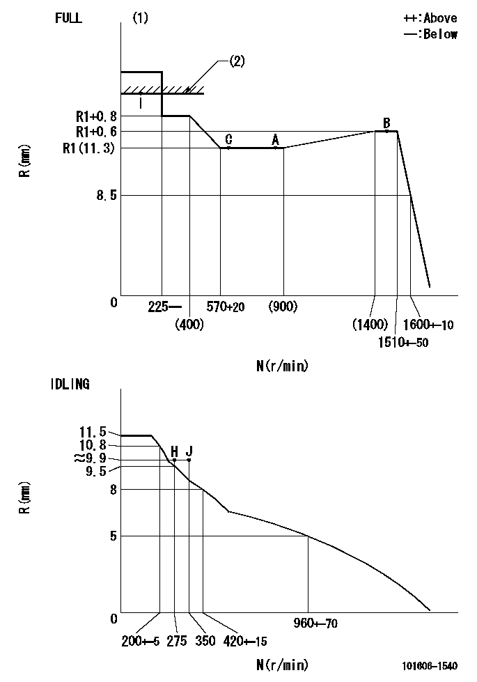
N:Pump speed
R:Rack position (mm)
(1)Torque cam stamping: T1
(2)RACK LIMIT
----------
T1=C69
----------
----------
T1=C69
----------
Speed control lever angle
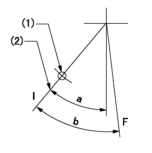
F:Full speed
I:Idle
(1)Use the hole at R = aa
(2)Stopper bolt set position 'H'
----------
aa=35mm
----------
a=41deg+-5deg b=(42deg)+-3deg
----------
aa=35mm
----------
a=41deg+-5deg b=(42deg)+-3deg
Stop lever angle

N:Engine manufacturer's normal use
S:Stop the pump.
(1)Set the stopper bolt at speed = rated point and rack position = aa (non-injection rack position). Confirm non-injection.
(2)After setting the stopper bolt , confirm non-injection at pump speed bb. Rack position = cc (non-injection rack position).
(3)Rack position = approximately dd
(4)Free (at shipping)
----------
aa=(7)mm bb=275r/min cc=(8)mm dd=17.4mm
----------
a=55.5deg+-5deg b=(27deg) c=17deg+-5deg
----------
aa=(7)mm bb=275r/min cc=(8)mm dd=17.4mm
----------
a=55.5deg+-5deg b=(27deg) c=17deg+-5deg
0000001501 MICRO SWITCH
Adjustment of the micro-switch
Adjust the bolt to obtain the following lever position when the micro-switch is ON.
(1)Speed N1
(2)Rack position Ra
----------
N1=400+-5r/min Ra=9.7mm
----------
----------
N1=400+-5r/min Ra=9.7mm
----------
Timing setting

(1)Pump vertical direction
(2)Position of timer's tooth at No 1 cylinder's beginning of injection
(3)B.T.D.C.: aa
(4)-
----------
aa=12deg
----------
a=(1deg)
----------
aa=12deg
----------
a=(1deg)
Information:
Fluids/Filters Recommendation
Literature InformationThis manual should be stored in the literature holder or in the literature storage area on the machine. Immediately replace this manual if lost, damaged, or unreadable.The information contained in this document is the most current information available for fluid maintenance and service products. Special maintenance and service products may be required for some machine compartments. Refer to the Operation and Maintenance Manual for your machine for the maintenance and service requirements. Read, study, and keep this manual with the product. This manual should be read carefully before using this product for the first time and before performing maintenance.Whenever a question arises regarding your product, or this publication, consult your dealer for the latest available information.SafetyRefer to the Operation and Maintenance Manual for your machine for all safety information. Read and understand the basic safety precautions listed in the Safety Section. In addition to safety precautions, this section identifies the text and locations of warning signs used on the machine.Read and understand the applicable precautions listed in the Maintenance and Operation Sections before operating or performing lubrication, maintenance, and repair on this machine.MaintenanceRefer to the Operation and Maintenance Manual for your machine to determine all maintenance requirements.Proper maintenance and repair are essential to keep the equipment and systems operating correctly. As the owner, you are responsible for the performance of the required maintenance listed in the Owner Manual, Operation and Maintenance Manual, and Service Manual.Maintenance Interval ScheduleUse the Maintenance Interval Schedule in the Operation and Maintenance Manual for your machine to determine servicing intervals. Use the service hour meter to determine servicing intervals. Calendar intervals shown (daily, weekly, monthly, etc.) can be used instead of service hour meter intervals if calendar intervals provide more convenient servicing schedules and approximate the indicated service hour meter reading. Recommended service should always be performed at the interval that occurs first.Under extremely severe, dusty, or wet operating conditions, more frequent lubrication and/or filter changes than is specified in the maintenance intervals chart might be necessary.Following the recommended maintenance intervals reduces the risk of excessive wear and potential failures of components.Aftermarket Products and Warranty
When auxiliary devices, accessories or consumables (filters, oil, additives, catalysts, fuel, etc.) made by other manufacturers are used on Cat products, the Caterpillar warranty is not affected simply because of such use. Failures that result from the installation or usage of other manufacturers auxiliary devices, accessories or consumables, however, are not Caterpillar factory defects and therefore are NOT covered by Caterpillar's warranty.Caterpillar is not in a position to evaluate the many auxiliary devices, accessories or consumables promoted by other manufacturers and their effect on Cat products. Installation or use of such items is at the discretion of the customer who assumes ALL risks for the effects that result from this usage.Furthermore, Caterpillar does not authorize the use of its trade name, trademark, or logo in a manner which implies our endorsement of these aftermarket products.