Information injection-pump assembly
ZEXEL
101606-1520
1016061520
Rating:
Cross reference number
ZEXEL
101606-1520
1016061520
Zexel num
Bosch num
Firm num
Name
Calibration Data:
Adjustment conditions
Test oil
1404 Test oil ISO4113 or {SAEJ967d}
1404 Test oil ISO4113 or {SAEJ967d}
Test oil temperature
degC
40
40
45
Nozzle and nozzle holder
105780-8140
Bosch type code
EF8511/9A
Nozzle
105780-0000
Bosch type code
DN12SD12T
Nozzle holder
105780-2080
Bosch type code
EF8511/9
Opening pressure
MPa
17.2
Opening pressure
kgf/cm2
175
Injection pipe
Outer diameter - inner diameter - length (mm) mm 6-2-600
Outer diameter - inner diameter - length (mm) mm 6-2-600
Overflow valve
131424-5520
Overflow valve opening pressure
kPa
255
221
289
Overflow valve opening pressure
kgf/cm2
2.6
2.25
2.95
Tester oil delivery pressure
kPa
157
157
157
Tester oil delivery pressure
kgf/cm2
1.6
1.6
1.6
Direction of rotation (viewed from drive side)
Left L
Left L
Injection timing adjustment
Direction of rotation (viewed from drive side)
Left L
Left L
Injection order
1-5-3-6-
2-4
Pre-stroke
mm
3.6
3.55
3.65
Beginning of injection position
Governor side NO.1
Governor side NO.1
Difference between angles 1
Cal 1-5 deg. 60 59.5 60.5
Cal 1-5 deg. 60 59.5 60.5
Difference between angles 2
Cal 1-3 deg. 120 119.5 120.5
Cal 1-3 deg. 120 119.5 120.5
Difference between angles 3
Cal 1-6 deg. 180 179.5 180.5
Cal 1-6 deg. 180 179.5 180.5
Difference between angles 4
Cyl.1-2 deg. 240 239.5 240.5
Cyl.1-2 deg. 240 239.5 240.5
Difference between angles 5
Cal 1-4 deg. 300 299.5 300.5
Cal 1-4 deg. 300 299.5 300.5
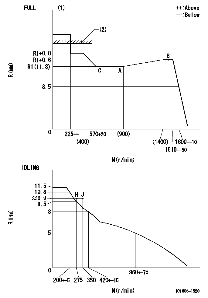
Injection quantity adjustment
Adjusting point
-
Rack position
11.3
Pump speed
r/min
850
850
850
Each cylinder's injection qty
mm3/st.
65.4
63.5
67.3
Basic
*
Fixing the rack
*
Standard for adjustment of the maximum variation between cylinders
*
Injection quantity adjustment_02
Adjusting point
H
Rack position
9.9+-0.5
Pump speed
r/min
275
275
275
Each cylinder's injection qty
mm3/st.
9.2
8.1
10.3
Fixing the rack
*
Standard for adjustment of the maximum variation between cylinders
*
Injection quantity adjustment_03
Adjusting point
A
Rack position
R1(11.3)
Pump speed
r/min
850
850
850
Average injection quantity
mm3/st.
65.4
64.4
66.4
Basic
*
Fixing the lever
*
Injection quantity adjustment_04
Adjusting point
B
Rack position
R1+0.6
Pump speed
r/min
1450
1450
1450
Average injection quantity
mm3/st.
81.2
77.2
85.2
Fixing the lever
*
Injection quantity adjustment_05
Adjusting point
C
Rack position
R1(11.3)
Pump speed
r/min
600
600
600
Average injection quantity
mm3/st.
49.5
45.5
53.5
Fixing the lever
*
Injection quantity adjustment_06
Adjusting point
I
Rack position
-
Pump speed
r/min
100
100
100
Average injection quantity
mm3/st.
80
75
85
Fixing the lever
*
Rack limit
*
Timer adjustment
Pump speed
r/min
1250--
Advance angle
deg.
0
0
0
Remarks
Start
Start
Timer adjustment_02
Pump speed
r/min
1200
Advance angle
deg.
0.5
Timer adjustment_03
Pump speed
r/min
1350
Advance angle
deg.
2.4
1.9
2.9
Timer adjustment_04
Pump speed
r/min
1500
Advance angle
deg.
5
4.5
5.5
Remarks
Finish
Finish
Test data Ex:
Governor adjustment
N:Pump speed
R:Rack position (mm)
(1)Torque cam stamping: T1
(2)RACK LIMIT
----------
T1=C69
----------
----------
T1=C69
----------
Speed control lever angle
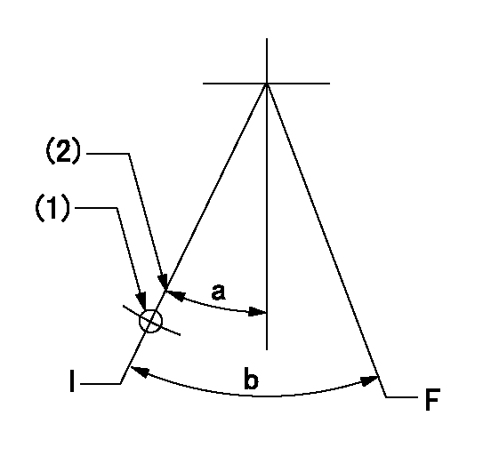
F:Full speed
I:Idle
(1)Use the hole at R = aa
(2)Stopper bolt set position 'H'
----------
aa=35mm
----------
a=33deg+-5deg b=(42deg)+-3deg
----------
aa=35mm
----------
a=33deg+-5deg b=(42deg)+-3deg
Stop lever angle
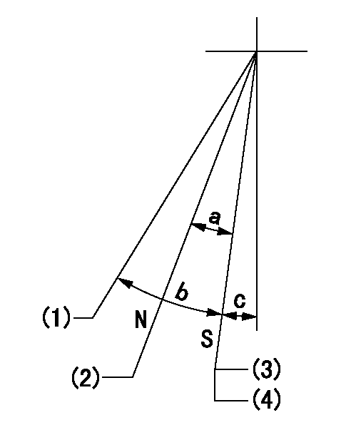
N:Engine manufacturer's normal use
S:Stop the pump.
(1)Free (at shipping)
(2)Non-injection rack position
(3)Set the stopper bolt at speed = rated point and rack position = aa (non-injection rack position). Confirm non-injection.
(4)After setting the stopper bolt , confirm non-injection at pump speed bb. Rack position = cc (non-injection rack position).
----------
aa=(7)mm bb=275r/min cc=(8)mm
----------
a=17deg+-5deg b=(27deg) c=2deg+-5deg
----------
aa=(7)mm bb=275r/min cc=(8)mm
----------
a=17deg+-5deg b=(27deg) c=2deg+-5deg
0000001501 MICRO SWITCH
Adjustment of the micro-switch
Adjust the bolt to obtain the following lever position when the micro-switch is ON.
(1)Speed N1
(2)Rack position Ra
----------
N1=400+-5r/min Ra=9.7mm
----------
----------
N1=400+-5r/min Ra=9.7mm
----------
Timing setting

(1)Pump vertical direction
(2)Position of timer's tooth at No 1 cylinder's beginning of injection
(3)B.T.D.C.: aa
(4)-
----------
aa=12deg
----------
a=(1deg)
----------
aa=12deg
----------
a=(1deg)
Information:
General
The objective of this information is to assist users in establishing a Preventive Maintenance Program for Standby Generator Sets or as an aid in evaluating their present programs.Standby Generator Sets may not be needed very often, but when they are, it is usually under emergency conditions. Maintenance of these standby units is very important. They must always be in excellent operating condition, ready to work under load at any time.Establishing a Preventive Maintenance Program will provide maximum availability of a standby generator set when needed, longer engine and generator life, and a minimum of expensive repairs.The recommended weekly maintenance checks can be performed by an operator. All yearly and three year maintenance should be performed by an authorized mechanic or your Caterpillar dealer.These guidelines are to be used with the information contained in the Operation and Maintenance Sections of this guide. The Operation and Maintenance sections of the guide will provide the necessary information on how to perform the checks and routine maintenance. Additional information can be obtained from the Generator and Engine Service Manuals, or contact your Caterpillar dealer for assistance.Inspection and Maintenance Agreements
Your Caterpillar dealer can establish an Inspection and Preventive Maintenance Program for your generator set to provide maximum reliability, increased engine and generator life, and minimize expensive repairs. Contact your Caterpillar dealer for details.Safety
Always make repairs with the engine stopped and the starting system disabled. When servicing the generator, make sure that switch gear and automatic transfer switches will not present a shock hazard. Lock them out on the generator being serviced.Record Keeping
Maintain a log or record keeping system to document all gauge readings, problems, repairs, and maintenance performed on the equipment.Space Heaters
Moisture is a natural enemy of generators and all electrical equipment. Every effort must be made to keep the generator as dry as possible. Space heaters should be operated inside the generator when it is not in use to maintain integrity of the generator windings.
Failure to comply with the following could result in personal injury or death.
* The Stop-Manual-Automatic (Auto Start/Stop) switch on the cranking panel must be at STOP position when performing maintenance or repair work on a standby generator set. This prevents the unit from starting if a power failure or voltage drop should occur while working on the unit. * To prevent personal injury due to accidental starting of the engine, disconnect the batteries or disable the starting system before doing maintenance or repair work.* Lock out all switch gear and automatic transfer switches associated with the generator while performing maintenance or repairs. Make sure no shock hazard exists.