Information injection-pump assembly
BOSCH
9 400 615 455
9400615455
ZEXEL
101606-1510
1016061510
MITSUBISHI
ME7H6006
me7h6006
Rating:
Include in #1:
101492-0772
as _
Cross reference number
BOSCH
9 400 615 455
9400615455
ZEXEL
101606-1510
1016061510
MITSUBISHI
ME7H6006
me7h6006
Zexel num
Bosch num
Firm num
Name
101606-1510
9 400 615 455
ME7H6006 MITSUBISHI
INJECTION-PUMP ASSEMBLY
6D15 K
6D15 K
Calibration Data:
Adjustment conditions
Test oil
1404 Test oil ISO4113 or {SAEJ967d}
1404 Test oil ISO4113 or {SAEJ967d}
Test oil temperature
degC
40
40
45
Nozzle and nozzle holder
105780-8140
Bosch type code
EF8511/9A
Nozzle
105780-0000
Bosch type code
DN12SD12T
Nozzle holder
105780-2080
Bosch type code
EF8511/9
Opening pressure
MPa
17.2
Opening pressure
kgf/cm2
175
Injection pipe
Outer diameter - inner diameter - length (mm) mm 6-2-600
Outer diameter - inner diameter - length (mm) mm 6-2-600
Overflow valve
131424-5520
Overflow valve opening pressure
kPa
255
221
289
Overflow valve opening pressure
kgf/cm2
2.6
2.25
2.95
Tester oil delivery pressure
kPa
157
157
157
Tester oil delivery pressure
kgf/cm2
1.6
1.6
1.6
Direction of rotation (viewed from drive side)
Left L
Left L
Injection timing adjustment
Direction of rotation (viewed from drive side)
Left L
Left L
Injection order
1-5-3-6-
2-4
Pre-stroke
mm
3.6
3.55
3.65
Beginning of injection position
Governor side NO.1
Governor side NO.1
Difference between angles 1
Cal 1-5 deg. 60 59.5 60.5
Cal 1-5 deg. 60 59.5 60.5
Difference between angles 2
Cal 1-3 deg. 120 119.5 120.5
Cal 1-3 deg. 120 119.5 120.5
Difference between angles 3
Cal 1-6 deg. 180 179.5 180.5
Cal 1-6 deg. 180 179.5 180.5
Difference between angles 4
Cyl.1-2 deg. 240 239.5 240.5
Cyl.1-2 deg. 240 239.5 240.5
Difference between angles 5
Cal 1-4 deg. 300 299.5 300.5
Cal 1-4 deg. 300 299.5 300.5
Injection quantity adjustment
Adjusting point
-
Rack position
11.45
Pump speed
r/min
850
850
850
Each cylinder's injection qty
mm3/st.
68.5
64.5
72.5
Basic
*
Fixing the rack
*
Standard for adjustment of the maximum variation between cylinders
*
Injection quantity adjustment_02
Adjusting point
H
Rack position
9.9+-0.5
Pump speed
r/min
275
275
275
Each cylinder's injection qty
mm3/st.
9.2
8.1
10.3
Fixing the rack
*
Standard for adjustment of the maximum variation between cylinders
*
Injection quantity adjustment_03
Adjusting point
A
Rack position
R1(11.45
)
Pump speed
r/min
850
850
850
Average injection quantity
mm3/st.
68.5
66.5
70.5
Basic
*
Fixing the lever
*
Injection quantity adjustment_04
Adjusting point
B
Rack position
R1+0.35
Pump speed
r/min
1450
1450
1450
Average injection quantity
mm3/st.
80
76
84
Fixing the lever
*
Injection quantity adjustment_05
Adjusting point
C
Rack position
R1-0.1
Pump speed
r/min
600
600
600
Average injection quantity
mm3/st.
50.5
46.5
54.5
Fixing the lever
*
Injection quantity adjustment_06
Adjusting point
I
Rack position
-
Pump speed
r/min
100
100
100
Average injection quantity
mm3/st.
80
75
85
Fixing the lever
*
Rack limit
*
Timer adjustment
Pump speed
r/min
1250--
Advance angle
deg.
0
0
0
Remarks
Start
Start
Timer adjustment_02
Pump speed
r/min
1200
Advance angle
deg.
0.5
Timer adjustment_03
Pump speed
r/min
1350
Advance angle
deg.
2.4
1.9
2.9
Timer adjustment_04
Pump speed
r/min
1500
Advance angle
deg.
5
4.5
5.5
Remarks
Finish
Finish
Test data Ex:
Governor adjustment
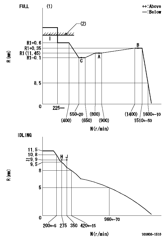
N:Pump speed
R:Rack position (mm)
(1)Torque cam stamping: T1
(2)RACK LIMIT
----------
T1=C74
----------
----------
T1=C74
----------
Speed control lever angle

F:Full speed
I:Idle
(1)Stopper bolt set position 'H'
----------
----------
a=18.5deg+-5deg b=(42deg)+-3deg
----------
----------
a=18.5deg+-5deg b=(42deg)+-3deg
Stop lever angle

N:Engine manufacturer's normal use
S:Stop the pump.
(1)Set the stopper bolt at speed = rated point and rack position = aa (non-injection rack position). Confirm non-injection.
(2)After setting the stopper bolt , confirm non-injection at pump speed bb. Rack position = cc (non-injection rack position).
(3)Rack position = approximately dd
(4)Free (at shipping)
----------
aa=(7)mm bb=275r/min cc=(8)mm dd=17.4mm
----------
a=38.5deg+-5deg b=(27deg) c=17deg+-5deg
----------
aa=(7)mm bb=275r/min cc=(8)mm dd=17.4mm
----------
a=38.5deg+-5deg b=(27deg) c=17deg+-5deg
0000001501 MICRO SWITCH
Adjustment of the micro-switch
Adjust the bolt to obtain the following lever position when the micro-switch is ON.
(1)Speed N1
(2)Rack position Ra
----------
N1=400+-5r/min Ra=9.7mm
----------
----------
N1=400+-5r/min Ra=9.7mm
----------
Timing setting

(1)Pump vertical direction
(2)Position of timer's tooth at No 1 cylinder's beginning of injection
(3)B.T.D.C.: aa
(4)-
----------
aa=12deg
----------
a=(1deg)
----------
aa=12deg
----------
a=(1deg)
Information:
2. Loosen the fuel injection line nut at the fuel pump, one at a time, with the engine running. Use a cloth or similar material to prevent fuel from spraying on hot exhaust component. Be sure to tighten each fuel line nut after the test, before the next fuel line nut is loosened. 3. When a cylinder is found where the loosened fuel line nut does not make a difference in engine performance or smoking, have that cylinder injection nozzle tested. Purge the fuel lines of air. 4. Check for any fuel leaks. Stop the engine by following the procedure in the Engine Stopping topic in this manual and correct any fuel leaks that may occur. To Remove and Install Injection Nozzles
Special tooling is required. Refer to the Service Manual for your engine to remove and install injection nozzles or contact your Caterpillar dealer for assistance.Starting Motor and Alternator
Inspect for Proper Operation
Electric Starting Motor
AlternatorFor good life of the air starting motor, the air supply should be free of dirt and water. A lubricator should be used with the starting system. Use 10 weight non-detergent engine oil above 0°C (32°F) or diesel fuel at temperatures below 0°C (32°F). See the Lubricant Specifications for the proper oil to use.One unscheduled failure caused by any of these components will cost more in downtime than maintaining them before failure. The cost incurred to maintain these components before failure as recommended could be significantly less than if the component fails. By maintaining these components before failure, unscheduled downtime and potential damage to other engine parts are reduced. The prevention of unscheduled downtime saves money and lowers operating costs.Caterpillar recommends that the most cost effective method of operation and maintenance for these components is to inspect the unit before it fails and make the decision to rebuild or exchange the components.Before deciding which repair method is best, make sure all of the options and costs associated with repair have been considered. Some considerations are:* The costs associated with using separate parts from inventory versus the cost of a repair kit.* Downtime costs while the product is being rebuilt or repaired.* Total parts and labor costs for repairs versus the actual Remanufactured cost.* Remanufactured components from Caterpillar (if available) are covered by a standard, factory warranty.Caterpillar Recommendation
To minimize downtime, Caterpillar recommends that the use of Remanufactured components (subject to availability) is the most cost effective option.Removal and Installation
Refer to the established procedure in the Service Manual for this engine to Remove and Install these components or contact your Caterpillar dealer for assistance.Turbochargers
Rebuild or Exchange
The cost incurred to maintain your turbochargers before failure as recommended could be significantly less than if you wait until your turbocharger fails. By maintaining your turbochargers before failure, you will minimize unscheduled downtime and reduce the chances for potential damage to other engine parts. If you choose to operate your engine until the turbochargers fail, your repair costs could be as much as twenty-five times or more compared
Have questions with 101606-1510?
Group cross 101606-1510 ZEXEL
Mitsubishi
101606-1510
9 400 615 455
ME7H6006
INJECTION-PUMP ASSEMBLY
6D15
6D15