Information injection-pump assembly
BOSCH
9 400 615 453
9400615453
ZEXEL
101606-1490
1016061490
MITSUBISHI
ME070570
me070570

Rating:
Service parts 101606-1490 INJECTION-PUMP ASSEMBLY:
1.
_
6.
COUPLING PLATE
7.
COUPLING PLATE
8.
_
9.
_
11.
Nozzle and Holder
ME035749
12.
Open Pre:MPa(Kqf/cm2)
21.6{220}
15.
NOZZLE SET
Include in #1:
101606-1490
as INJECTION-PUMP ASSEMBLY
Include in #2:
104746-1871
as _
Cross reference number
BOSCH
9 400 615 453
9400615453
ZEXEL
101606-1490
1016061490
MITSUBISHI
ME070570
me070570
Zexel num
Bosch num
Firm num
Name
Calibration Data:
Adjustment conditions
Test oil
1404 Test oil ISO4113 or {SAEJ967d}
1404 Test oil ISO4113 or {SAEJ967d}
Test oil temperature
degC
40
40
45
Nozzle and nozzle holder
105780-8140
Bosch type code
EF8511/9A
Nozzle
105780-0000
Bosch type code
DN12SD12T
Nozzle holder
105780-2080
Bosch type code
EF8511/9
Opening pressure
MPa
17.2
Opening pressure
kgf/cm2
175
Injection pipe
Outer diameter - inner diameter - length (mm) mm 6-2-600
Outer diameter - inner diameter - length (mm) mm 6-2-600
Overflow valve
131424-5520
Overflow valve opening pressure
kPa
255
221
289
Overflow valve opening pressure
kgf/cm2
2.6
2.25
2.95
Tester oil delivery pressure
kPa
157
157
157
Tester oil delivery pressure
kgf/cm2
1.6
1.6
1.6
Direction of rotation (viewed from drive side)
Left L
Left L
Injection timing adjustment
Direction of rotation (viewed from drive side)
Left L
Left L
Injection order
1-5-3-6-
2-4
Pre-stroke
mm
2.9
2.85
2.95
Beginning of injection position
Governor side NO.1
Governor side NO.1
Difference between angles 1
Cal 1-5 deg. 60 59.5 60.5
Cal 1-5 deg. 60 59.5 60.5
Difference between angles 2
Cal 1-3 deg. 120 119.5 120.5
Cal 1-3 deg. 120 119.5 120.5
Difference between angles 3
Cal 1-6 deg. 180 179.5 180.5
Cal 1-6 deg. 180 179.5 180.5
Difference between angles 4
Cyl.1-2 deg. 240 239.5 240.5
Cyl.1-2 deg. 240 239.5 240.5
Difference between angles 5
Cal 1-4 deg. 300 299.5 300.5
Cal 1-4 deg. 300 299.5 300.5
Injection quantity adjustment
Adjusting point
A
Rack position
10
Pump speed
r/min
1100
1100
1100
Average injection quantity
mm3/st.
87
86
88
Max. variation between cylinders
%
0
-2.5
2.5
Basic
*
Fixing the lever
*
Injection quantity adjustment_02
Adjusting point
B
Rack position
8.3+-0.5
Pump speed
r/min
385
385
385
Average injection quantity
mm3/st.
21.5
20
23
Max. variation between cylinders
%
0
-15
15
Fixing the rack
*
Timer adjustment
Pump speed
r/min
1250--
Advance angle
deg.
0
0
0
Remarks
Start
Start
Timer adjustment_02
Pump speed
r/min
1200
Advance angle
deg.
0.5
Timer adjustment_03
Pump speed
r/min
-
Advance angle
deg.
2
2
2
Remarks
Measure the actual speed, stop
Measure the actual speed, stop
Test data Ex:
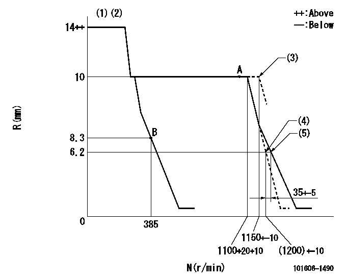
Governor adjustment

N:Pump speed
R:Rack position (mm)
(1)Notch fixed: K
(2)Deliver without the torque control spring operating.
(3)At shipping
(4)Main spring setting
(5)Set idle sub-spring
----------
K=15
----------
----------
K=15
----------
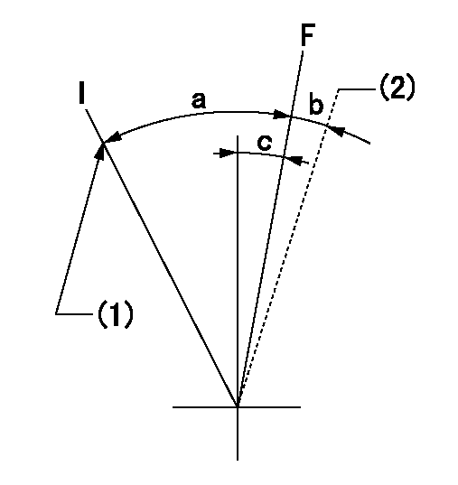
Speed control lever angle

F:Full speed
I:Idle
(1)Stopper bolt setting
(2)At shipping
----------
----------
a=23deg+-5deg b=(2deg) c=11deg+-5deg
----------
----------
a=23deg+-5deg b=(2deg) c=11deg+-5deg
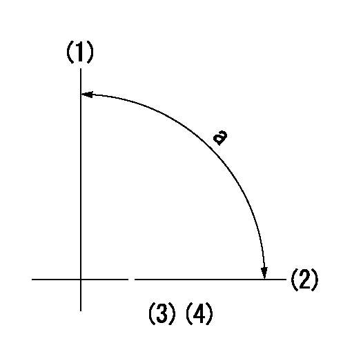
Stop lever angle

N:Pump normal
S:Stop the pump.
----------
----------
a=26deg+-5deg b=53deg+-5deg
----------
----------
a=26deg+-5deg b=53deg+-5deg
Timing setting

(1)Pump vertical direction
(2)Position of gear mark '2' at No 1 cylinder's beginning of injection
(3)B.T.D.C.: aa
(4)-
----------
aa=19deg
----------
a=(90deg)
----------
aa=19deg
----------
a=(90deg)
Information:
You must read and understand the warnings and instructions contained in the Safety section of this manual before performing any operation or maintenance procedures.Before proceeding with this maintenance interval, perform previous maintenance interval requirements. Perform the maintenance at the interval listed in the Maintenance Schedule for your engine.Engine Protection Controls
Inspect For Proper Operation
The engine protective alarm and shutoff controls must be tested, inspected and checked by an authorized Caterpillar dealer at least every year or 1000 hours for proper operation. The manual shutoff functions should be tested to ensure proper operation and protection to the engine. Refer to Engine Control, Monitoring and Protection in the Operation Section in this Manual. Have the checks made by a qualified mechanic. Consult your authorized Caterpillar engine dealer, or refer to the Service Manual for your engine. Check Alarm and Shutdown Settings
Check for loose, broken, or damaged wiring or components. Check the condition of all sensors and wiring. Repair or replace any broken or malfunctioning sensors before they become a problem. The inspection only takes a few minutes and could avert a potential problem that could cause your engine to fail. Check GSC Display Window Readings
Refer to the operating parameters in the Engine Control, Monitoring and Protection topic.While operating, observe all GSC display window readings hourly, especially the engine oil pressure, fuel pressure and coolant temperature.Operational Checks
Start the engine. Use the starting procedure found in the Engine Starting topic in this publication.The operational checks are intended to check the engine starting and stopping, lubrication and fuel systems as well as overall operation. The checks should take no longer than five minutes to complete. Longer periods of operation are not required. A more thorough Performance Analysis should be performed with the engine operating under load.Automatic Switches
Check that all switches are in proper position for automatic start. The shutoff controls must be checked so that they function properly when they are required. To prevent damage to the engine while performing the test, only authorized personnel or your Caterpillar dealer should perform the checks.SR4 Generator
Make sure residual voltage in the rotor, stator and the generator is discharged.If this generator is to be connected to a utility electrical distribution system, it must be isolated from the distribution system by means of:a. Opening the main switch in the case of the generator temporarily connected to the system or,b. A double throw (transfer) switch in the case of a permanent connection to the system.Failure to do so could result in personal injury or death due to electrical shock. This warning does not apply when a generator and utility distribution system are designed and approved by the utility to run in parallel.
Before working inside the generator, make sure that the starting motor can not be activated by any automatic or manual signal.Electronic components in the regulator can be damaged during generator operation if contact is made between the part and ground.
Check Winding Insulation Resistance
When the engine-generator is operating, voltages up to 600V are present in these areas near