Information injection-pump assembly
BOSCH
9 400 615 450
9400615450
ZEXEL
101606-1460
1016061460
MITSUBISHI
ME7H6010
me7h6010

Rating:
Include in #2:
104746-1860
as _
Cross reference number
BOSCH
9 400 615 450
9400615450
ZEXEL
101606-1460
1016061460
MITSUBISHI
ME7H6010
me7h6010
Zexel num
Bosch num
Firm num
Name
101606-1460
9 400 615 450
ME7H6010 MITSUBISHI
INJECTION-PUMP ASSEMBLY
6D14 K
6D14 K
Calibration Data:
Adjustment conditions
Test oil
1404 Test oil ISO4113 or {SAEJ967d}
1404 Test oil ISO4113 or {SAEJ967d}
Test oil temperature
degC
40
40
45
Nozzle and nozzle holder
105780-8140
Bosch type code
EF8511/9A
Nozzle
105780-0000
Bosch type code
DN12SD12T
Nozzle holder
105780-2080
Bosch type code
EF8511/9
Opening pressure
MPa
17.2
Opening pressure
kgf/cm2
175
Injection pipe
Outer diameter - inner diameter - length (mm) mm 6-2-600
Outer diameter - inner diameter - length (mm) mm 6-2-600
Overflow valve
131424-5520
Overflow valve opening pressure
kPa
255
221
289
Overflow valve opening pressure
kgf/cm2
2.6
2.25
2.95
Tester oil delivery pressure
kPa
157
157
157
Tester oil delivery pressure
kgf/cm2
1.6
1.6
1.6
Direction of rotation (viewed from drive side)
Left L
Left L
Injection timing adjustment
Direction of rotation (viewed from drive side)
Left L
Left L
Injection order
1-5-3-6-
2-4
Pre-stroke
mm
3.3
3.25
3.35
Beginning of injection position
Governor side NO.1
Governor side NO.1
Difference between angles 1
Cal 1-5 deg. 60 59.5 60.5
Cal 1-5 deg. 60 59.5 60.5
Difference between angles 2
Cal 1-3 deg. 120 119.5 120.5
Cal 1-3 deg. 120 119.5 120.5
Difference between angles 3
Cal 1-6 deg. 180 179.5 180.5
Cal 1-6 deg. 180 179.5 180.5
Difference between angles 4
Cyl.1-2 deg. 240 239.5 240.5
Cyl.1-2 deg. 240 239.5 240.5
Difference between angles 5
Cal 1-4 deg. 300 299.5 300.5
Cal 1-4 deg. 300 299.5 300.5
Injection quantity adjustment
Adjusting point
-
Rack position
11
Pump speed
r/min
850
850
850
Each cylinder's injection qty
mm3/st.
65
63
67
Basic
*
Fixing the rack
*
Standard for adjustment of the maximum variation between cylinders
*
Injection quantity adjustment_02
Adjusting point
H
Rack position
9.5+-0.5
Pump speed
r/min
275
275
275
Each cylinder's injection qty
mm3/st.
10.5
9
12
Fixing the rack
*
Standard for adjustment of the maximum variation between cylinders
*
Injection quantity adjustment_03
Adjusting point
A
Rack position
R1(11)
Pump speed
r/min
850
850
850
Average injection quantity
mm3/st.
65
64
66
Basic
*
Fixing the lever
*
Injection quantity adjustment_04
Adjusting point
B
Rack position
R1(11)
Pump speed
r/min
1450
1450
1450
Average injection quantity
mm3/st.
77.5
75.5
79.5
Fixing the lever
*
Injection quantity adjustment_05
Adjusting point
C
Rack position
R1+0.4
Pump speed
r/min
600
600
600
Average injection quantity
mm3/st.
59.7
55.7
63.7
Fixing the lever
*
Injection quantity adjustment_06
Adjusting point
I
Rack position
-
Pump speed
r/min
100
100
100
Average injection quantity
mm3/st.
90
70
110
Fixing the lever
*
Rack limit
*
Timer adjustment
Pump speed
r/min
1250--
Advance angle
deg.
0
0
0
Remarks
Start
Start
Timer adjustment_02
Pump speed
r/min
1200
Advance angle
deg.
0.5
Timer adjustment_03
Pump speed
r/min
1350
Advance angle
deg.
2.4
1.9
2.9
Timer adjustment_04
Pump speed
r/min
1500
Advance angle
deg.
5
4.5
5.5
Remarks
Finish
Finish
Test data Ex:
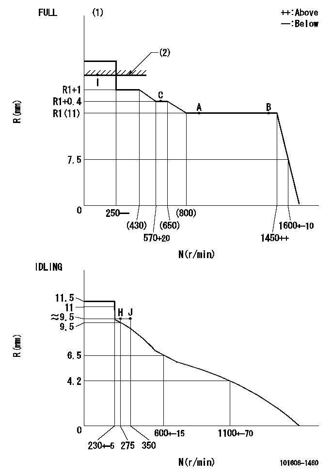
Governor adjustment

N:Pump speed
R:Rack position (mm)
(1)Torque cam stamping: T1
(2)RACK LIMIT
----------
T1=C67
----------
----------
T1=C67
----------
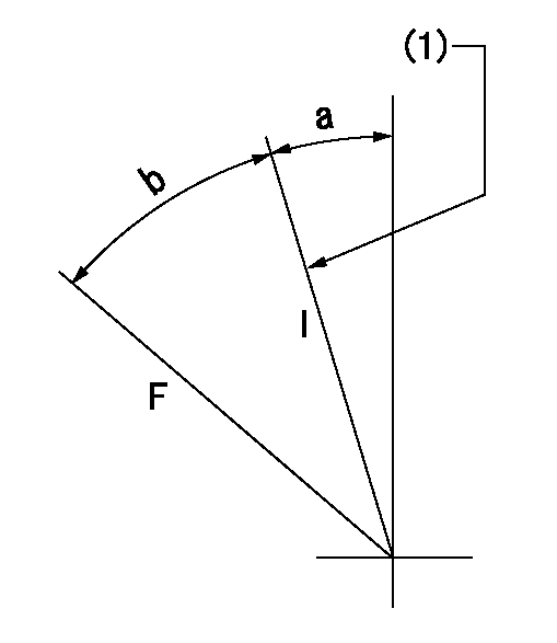
Speed control lever angle

F:Full speed
I:Idle
(1)Stopper bolt set position 'H'
----------
----------
a=18.5deg+-5deg b=40.5deg+-3deg
----------
----------
a=18.5deg+-5deg b=40.5deg+-3deg
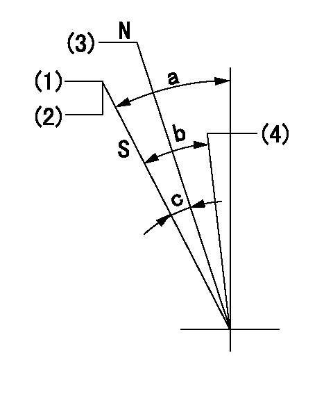
Stop lever angle

N:Engine manufacturer's normal use
S:Stop the pump.
(1)Set the stopper bolt at speed = rated point and rack position = aa (non-injection rack position). Confirm non-injection.
(2)After setting the stopper bolt , confirm non-injection at pump speed bb. Rack position = cc (non-injection rack position).
(3)Rack position = approximately dd
(4)Free (at shipping)
----------
aa=5.4-0.5mm bb=275r/min cc=(7.4)mm dd=17.4mm
----------
a=38.5deg+-5deg b=(27deg) c=17deg+-5deg
----------
aa=5.4-0.5mm bb=275r/min cc=(7.4)mm dd=17.4mm
----------
a=38.5deg+-5deg b=(27deg) c=17deg+-5deg
0000001501 MICRO SWITCH
Adjustment of the micro-switch
Adjust the bolt to obtain the following lever position when the micro-switch is ON.
(1)Speed N1
(2)Rack position Ra
----------
N1=400+-5r/min Ra=9.2mm
----------
----------
N1=400+-5r/min Ra=9.2mm
----------
Timing setting

(1)Pump vertical direction
(2)Position of timer's tooth at No 1 cylinder's beginning of injection
(3)B.T.D.C.: aa
(4)-
----------
aa=13deg
----------
a=(0deg)
----------
aa=13deg
----------
a=(0deg)
Information:
USE FUEL CONSUMPTION, SERVICE HOURS OR TIME INTERVAL, WHICHEVER OCCURS FIRST.Daily
Walk-Around Inspection - Inspect engine, radiator and generator/control panel for dirt & debris, moisture, foreign objects, loose or broken fittings and wires, guards and components. Repair as necessary Engine Crankcase - Check oil level Cooling System - Check coolant level, Check for proper operation of coolant heater Air Cleaner Indicator - Check Air Starting Motor (If Equipped) - Check level; Drain water SR4 Generator - Check frequency (rpm) and generated voltage for proper settings and stability; record readingsEvery 250 Hours or 25 000 L (6500 gal) of Fuel*
Scheduled Oil Sampling (S O S)** - Obtain Engine Oil and Filters - Replace Fuel System - Drain water & sediment from tank; Replace final filter/Clean primary filter Cooling System - Test for coolant additive concentration; Add liquid coolant additive; Clean radiator fins Crankcase Breathers - Clean Batteries - Clean/Inspect and check electrolyte level Belts, Hoses and Clamps - Inspect/Check Engine Air Cleaners - Clean/Replace SR4 Generator - Check space heater (if equipped) Engine Speed Sensors (Magnetic Pickup) - Inspect/Clean at first oil change Valve Lash** - Check/Adjust at first oil changeEvery 1000 Hours or 100 000 L (26,000 gal) of Fuel*
Engine Protection Controls - Inspect for proper operation SR4 Generator - Check windings and record megohmeter readings (Refer to SEHS9124)Every 3000 Hours or 300 000 L (78,000 gal) of Fuel*
Engine Valve Lash - Check/Adjust, Inspect valve rotators Turbocharger - Inspect for proper operation Engine Mounts and Crankshaft Vibration Damper - Inspect/Check Cooling System - Clean/Flush/Change coolant and replace thermostat SR4 Generator - Lubricate bearings (Refer to SEBU6150) PAR Analysis - ObtainEvery 5000 Hours or 500 000 L (130,000 gal) of Fuel*
Fuel Injection Nozzles - Test/Exchange Starting Motor and Alternator - Inpect for proper operation Turbochargers - Inspect/Rebuild or Exchange Jacket Water Pump - Inspect/Rebuild or Exchange Engine Speed Sensors (Magnetic Pickup) - Inspect/CleanOverhaul Every 10,000 Hours or 1 000 000 L (260,000 gal) of Fuel*
Cylinder Heads, Oil Pump, Fuel Transfer Pump - Inspect/Rebuild or Exchange Piston Rings, Main Bearings, Rod Bearings, Valve Rotators and Crankshaft Seals - Install new Fuel Injection Nozzles and Fuel Injection Pump - Test Connecting Rods, Pistons, Cylinder Liners, Crankshaft, Camshaft, Cam Bearings, Damper, Fuel Pump Camshaft, Cam Followers and Fuel Racks - Inspect/Replace Gear Train Gears & Bushings and Driven Unit Alignment Oil Cooler and Aftercooler Core - Clean/Test Coolant Analysis - Obtain SR4 Generator - Inspect/Clean windings*First Perform Previous Service Hour Items Caterpillar suggests that fuel consumption be used as the preferred method of determining maintenance intervals. Fuel consumption/Hours to Overhaul interval will vary depending on the proper application of your engine rating and maintenance practices.
Have questions with 101606-1460?
Group cross 101606-1460 ZEXEL
Mitsubishi
Mitsubishi
101606-1460
9 400 615 450
ME7H6010
INJECTION-PUMP ASSEMBLY
6D14
6D14