Information injection-pump assembly
BOSCH
9 400 615 437
9400615437
ZEXEL
101606-1310
1016061310
MITSUBISHI
ME056669
me056669
Rating:
Service parts 101606-1310 INJECTION-PUMP ASSEMBLY:
1.
_
7.
COUPLING PLATE
8.
_
9.
_
11.
Nozzle and Holder
12.
Open Pre:MPa(Kqf/cm2)
21.6(220)

15.
NOZZLE SET
Include in #1:
101606-1310
as INJECTION-PUMP ASSEMBLY
Include in #2:
104746-6062
as _
Cross reference number
BOSCH
9 400 615 437
9400615437
ZEXEL
101606-1310
1016061310
MITSUBISHI
ME056669
me056669
Zexel num
Bosch num
Firm num
Name
101606-1310
9 400 615 437
ME056669 MITSUBISHI
INJECTION-PUMP ASSEMBLY
6D22 * K
6D22 * K
Calibration Data:
Adjustment conditions
Test oil
1404 Test oil ISO4113 or {SAEJ967d}
1404 Test oil ISO4113 or {SAEJ967d}
Test oil temperature
degC
40
40
45
Nozzle and nozzle holder
105780-8140
Bosch type code
EF8511/9A
Nozzle
105780-0000
Bosch type code
DN12SD12T
Nozzle holder
105780-2080
Bosch type code
EF8511/9
Opening pressure
MPa
17.2
Opening pressure
kgf/cm2
175
Injection pipe
Outer diameter - inner diameter - length (mm) mm 6-2-600
Outer diameter - inner diameter - length (mm) mm 6-2-600
Overflow valve
131424-5120
Overflow valve opening pressure
kPa
255
221
289
Overflow valve opening pressure
kgf/cm2
2.6
2.25
2.95
Tester oil delivery pressure
kPa
157
157
157
Tester oil delivery pressure
kgf/cm2
1.6
1.6
1.6
Direction of rotation (viewed from drive side)
Right R
Right R
Injection timing adjustment
Direction of rotation (viewed from drive side)
Right R
Right R
Injection order
1-5-3-6-
2-4
Pre-stroke
mm
4.5
4.45
4.55
Beginning of injection position
Governor side NO.1
Governor side NO.1
Difference between angles 1
Cal 1-5 deg. 60 59.5 60.5
Cal 1-5 deg. 60 59.5 60.5
Difference between angles 2
Cal 1-3 deg. 120 119.5 120.5
Cal 1-3 deg. 120 119.5 120.5
Difference between angles 3
Cal 1-6 deg. 180 179.5 180.5
Cal 1-6 deg. 180 179.5 180.5
Difference between angles 4
Cyl.1-2 deg. 240 239.5 240.5
Cyl.1-2 deg. 240 239.5 240.5
Difference between angles 5
Cal 1-4 deg. 300 299.5 300.5
Cal 1-4 deg. 300 299.5 300.5
Injection quantity adjustment
Adjusting point
-
Rack position
9.6
Pump speed
r/min
700
700
700
Each cylinder's injection qty
mm3/st.
112
108.6
115.4
Basic
*
Fixing the rack
*
Standard for adjustment of the maximum variation between cylinders
*
Injection quantity adjustment_02
Adjusting point
C
Rack position
8+-0.5
Pump speed
r/min
225
225
225
Each cylinder's injection qty
mm3/st.
18.5
15.7
21.3
Fixing the rack
*
Standard for adjustment of the maximum variation between cylinders
*
Injection quantity adjustment_03
Adjusting point
A
Rack position
R1(9.6)
Pump speed
r/min
700
700
700
Average injection quantity
mm3/st.
112
111
113
Basic
*
Fixing the lever
*
Injection quantity adjustment_04
Adjusting point
B
Rack position
R1(9.6)
Pump speed
r/min
1100
1100
1100
Average injection quantity
mm3/st.
113.5
111
116
Difference in delivery
mm3/st.
9
9
9
Fixing the lever
*
Injection quantity adjustment_05
Adjusting point
E
Rack position
-
Pump speed
r/min
100
100
100
Average injection quantity
mm3/st.
140
120
160
Fixing the lever
*
Remarks
After startup boost setting
After startup boost setting
Timer adjustment
Pump speed
r/min
850--
Advance angle
deg.
0
0
0
Remarks
Start
Start
Timer adjustment_02
Pump speed
r/min
800
Advance angle
deg.
0.5
Timer adjustment_03
Pump speed
r/min
1000
Advance angle
deg.
0.9
0.4
1.4
Timer adjustment_04
Pump speed
r/min
1150
Advance angle
deg.
3
2.5
3.5
Timer adjustment_05
Pump speed
r/min
-
Advance angle
deg.
4
4
5
Remarks
Measure the actual speed, stop
Measure the actual speed, stop
Test data Ex:
Governor adjustment
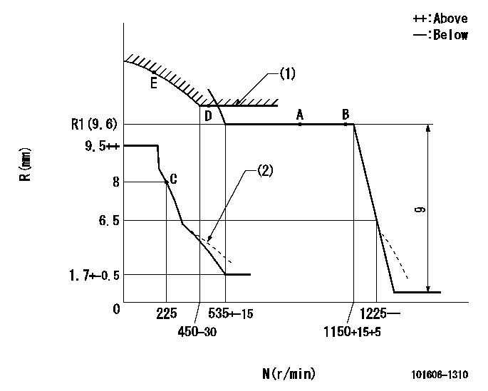
N:Pump speed
R:Rack position (mm)
(1)Excess fuel setting for starting: SXL
(2)Damper spring setting: DL
----------
SXL=R1(9.6)+0.2mm DL=6-0.2mm
----------
----------
SXL=R1(9.6)+0.2mm DL=6-0.2mm
----------
Speed control lever angle

F:Full speed
----------
----------
a=10deg+-5deg
----------
----------
a=10deg+-5deg
0000000901
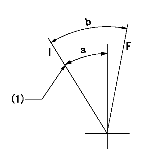
F:Full load
I:Idle
(1)Stopper bolt setting
----------
----------
a=24deg+-5deg b=29deg+-3deg
----------
----------
a=24deg+-5deg b=29deg+-3deg
Stop lever angle
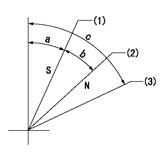
N:Pump normal
S:Stop the pump.
(1)Rack position = aa, stopper bolt setting
(2)Rack position bb
(3)Free (at delivery)
----------
aa=5.5-0.5mm bb=16mm
----------
a=12.5deg+5deg-7deg b=34deg+-5deg c=(66.5deg)
----------
aa=5.5-0.5mm bb=16mm
----------
a=12.5deg+5deg-7deg b=34deg+-5deg c=(66.5deg)
0000001501 MICRO SWITCH
Adjustment of the micro-switch
Adjust the bolt to obtain the following lever position when the micro-switch is ON.
(1)Speed N1
(2)Rack position Ra
----------
N1=325+-5r/min Ra=7.3mm
----------
----------
N1=325+-5r/min Ra=7.3mm
----------
0000001601 ACS
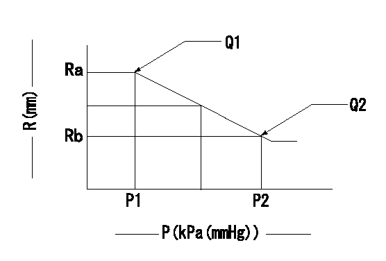
Aneroid compensator adjustment
(1)Adjust the clearance between the aneroid compensator's main body and the push rod to L1.
(2)Pump speed N1 at load lever's full position.
(3)Screw in the aneroid compensator body to obtain the performance shown in the graph above.
----------
L1=0.1~0.5mm N1=700r/min
----------
Ra=9.6mm Rb=8.7mm P1=(88.8)kPa((666)mmHg) P2=69.3+-0.7kPa(520+-5mmHg) Q1=112+-1cm3/1000st Q2=-
----------
L1=0.1~0.5mm N1=700r/min
----------
Ra=9.6mm Rb=8.7mm P1=(88.8)kPa((666)mmHg) P2=69.3+-0.7kPa(520+-5mmHg) Q1=112+-1cm3/1000st Q2=-
Timing setting

(1)Pump vertical direction
(2)Coupling's key groove position at No 1 cylinder's beginning of injection
(3)-
(4)-
----------
----------
a=(7deg)
----------
----------
a=(7deg)
Information:
Use Again - if wear on contact surfaces cannot be felt with a seal pick.
Illustration 46 g06346577
Rack control and limiting sleeve.
Use Again - if wear on contact surfaces cannot be felt with a seal pick.Riser Shaft and Pin
Illustration 47 g06346580
Riser shaft.
Use Again - if there is no wear step on the shaft, which can be felt with a seal pick. If a step is present, it will generally occur near the center of the shaft.
Illustration 48 g06346583
Normal wear on pin at end of riser shaft.
Use Again
Illustration 49 g06346588
Pin with material eroded away near the center relief.
Do Not Use AgainFlyweight and Dowel
Illustration 50 g06346593
Flyweight toe with gouges near dowel hole.
Do Not Use Again - if wear marks can be felt with a seal pick.
Illustration 51 g06346599
Flyweight toe wear.
Do Not Use Again
Illustration 52 g06346602
Flyweight toe wear.
Do Not Use Again - if there are any signs of "flat spots". Worn flyweight toes may be highly polished so that flat spots are difficult to feel. Hold the flyweight toe surface in bright light and watch for changes in reflection in worn areas. Use a new flyweight toe for comparison.
Illustration 53 g06346609
Acceptable wear on flyweight dowel.
Use Again - if wear cannot be felt with a seal pick.
Illustration 54 g06346611
Heavy wear on flyweight dowel.
Do Not Use AgainNote: Examine the dowel seating area on the flyweight carrier. If there is any apparent wear, reinstall dowels in the unused positions, 90 degrees from original position.Bearing Assembly
Illustration 55 g06346614
The bearing (white collar) shown in position on the FARC diaphragm retainer (Type V, VI, and VII Governors) shows wear.
Do Not Use AgainGovernor Spring Seat
Illustration 56 g06346615
Governor spring seat with typical wear.
Use Again - if there are no gouges to surfaces (1) on the spring seating area.Spring Pack
Illustration 57 g06346618
End view of governor spring pack.
Use Again - after realignment.Note the off-center position of the internal springs with respect to the outside spring. This can cause governor instability, which results in surging. Rotate the springs on their seat so that the inner springs are aligned (centered) with respect to the outer spring. Remove sharp edges (A) from the inside diameter of the flat surface on the springs to ensure springs seat properly.
Have questions with 101606-1310?
Group cross 101606-1310 ZEXEL
Mitsubishi
101606-1310
9 400 615 437
ME056669
INJECTION-PUMP ASSEMBLY
6D22
6D22