Information injection-pump assembly
ZEXEL
101606-1290
1016061290
MITSUBISHI
ME047486
me047486
Rating:
Cross reference number
ZEXEL
101606-1290
1016061290
MITSUBISHI
ME047486
me047486
Zexel num
Bosch num
Firm num
Name
101606-1290
ME047486 MITSUBISHI
INJECTION-PUMP ASSEMBLY
6D16 * K
6D16 * K
Calibration Data:
Adjustment conditions
Test oil
1404 Test oil ISO4113 or {SAEJ967d}
1404 Test oil ISO4113 or {SAEJ967d}
Test oil temperature
degC
40
40
45
Nozzle and nozzle holder
105780-8140
Bosch type code
EF8511/9A
Nozzle
105780-0000
Bosch type code
DN12SD12T
Nozzle holder
105780-2080
Bosch type code
EF8511/9
Opening pressure
MPa
17.2
Opening pressure
kgf/cm2
175
Injection pipe
Outer diameter - inner diameter - length (mm) mm 6-2-600
Outer diameter - inner diameter - length (mm) mm 6-2-600
Overflow valve
131424-5520
Overflow valve opening pressure
kPa
255
221
289
Overflow valve opening pressure
kgf/cm2
2.6
2.25
2.95
Tester oil delivery pressure
kPa
157
157
157
Tester oil delivery pressure
kgf/cm2
1.6
1.6
1.6
Direction of rotation (viewed from drive side)
Left L
Left L
Injection timing adjustment
Direction of rotation (viewed from drive side)
Left L
Left L
Injection order
1-5-3-6-
2-4
Pre-stroke
mm
3.3
3.25
3.35
Beginning of injection position
Governor side NO.1
Governor side NO.1
Difference between angles 1
Cal 1-5 deg. 60 59.5 60.5
Cal 1-5 deg. 60 59.5 60.5
Difference between angles 2
Cal 1-3 deg. 120 119.5 120.5
Cal 1-3 deg. 120 119.5 120.5
Difference between angles 3
Cal 1-6 deg. 180 179.5 180.5
Cal 1-6 deg. 180 179.5 180.5
Difference between angles 4
Cyl.1-2 deg. 240 239.5 240.5
Cyl.1-2 deg. 240 239.5 240.5
Difference between angles 5
Cal 1-4 deg. 300 299.5 300.5
Cal 1-4 deg. 300 299.5 300.5
Injection quantity adjustment
Adjusting point
A
Rack position
9.2
Pump speed
r/min
1400
1400
1400
Average injection quantity
mm3/st.
73.8
72.8
74.8
Max. variation between cylinders
%
0
-2.5
2.5
Basic
*
Fixing the lever
*
Injection quantity adjustment_02
Adjusting point
B
Rack position
8+-0.5
Pump speed
r/min
350
350
350
Average injection quantity
mm3/st.
12.6
11.1
14.1
Max. variation between cylinders
%
0
-15
15
Fixing the rack
*
Timer adjustment
Pump speed
r/min
850--
Advance angle
deg.
0
0
0
Remarks
Start
Start
Timer adjustment_02
Pump speed
r/min
800
Advance angle
deg.
0.5
Timer adjustment_03
Pump speed
r/min
1400
Advance angle
deg.
5
4.5
5.5
Remarks
Finish
Finish
Test data Ex:
Governor adjustment
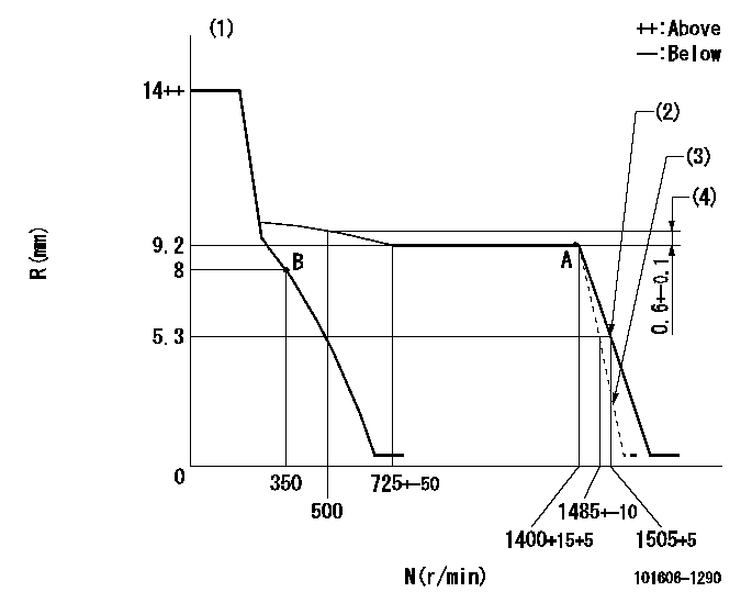
N:Pump speed
R:Rack position (mm)
(1)Target notch: K
(2)Set idle sub-spring
(3)Main spring setting
(4)Rack difference between N = N1 and N = N2
----------
K=11 N1=1400r/min N2=500r/min
----------
----------
K=11 N1=1400r/min N2=500r/min
----------
Speed control lever angle

F:Full speed
I:Idle
(1)Stopper bolt setting
----------
----------
a=27deg+-5deg b=17deg+-5deg
----------
----------
a=27deg+-5deg b=17deg+-5deg
Stop lever angle

N:Pump normal
S:Stop the pump.
----------
----------
a=26deg+-5deg b=53deg+-5deg
----------
----------
a=26deg+-5deg b=53deg+-5deg
Timing setting

(1)Pump vertical direction
(2)Position of gear mark 'Z' at No 1 cylinder's beginning of injection
(3)B.T.D.C.: aa
(4)-
----------
aa=18deg
----------
a=(90deg)
----------
aa=18deg
----------
a=(90deg)
Information:
Abnormal engine running, smoke emission, and engine knock can be symptoms of nozzle malfunction. Each nozzle must be isolated one at a time in order to determine the malfunctioning nozzle.1. Start the engine.
A nozzle will be damaged if the top of the nozzle turns in the body. The engine will be damaged if a defective nozzle is used because the fuel spray pattern that comes out of the nozzle will be incorrect. Nozzles can be permanently damaged by twisting if only one wrench is used to loosen or tighten the fuel line nuts. Do NOT let the tops of the nozzles turn when the fuel lines are loosened. Use one wrench to hold the nozzle and another to loosen the fuel line nut.
2. Loosen each fuel line nut at the fuel injection pump, one at a time. A cloth or similar material must be used to prevent fuel from spraying on the hot exhaust components. Tighten each nut before loosening the next nut.3. A defective nozzle may be identified when a fuel line nut is loosened and: * the exhaust smoking is partially or completely eliminated* engine performance is not affectedA nozzle suspected of being defective should be removed. A new nozzle should be installed in the cylinder to determine if the removed nozzle is defective.Removing and Installing Fuel Injection Nozzles
Special tooling is required to remove and install nozzles. Refer to the Service Manual for information. Consult with your Caterpillar dealer for assistance.Inspect, Rebuild, or Exchange
If the engine is operated until the components fail, additional engine damage can result. Caterpillar recommends that the following components be inspected in order to ensure reliable engine performance:* Jacket Water Pump* Raw/Sea Water Pump* Alternator* Starting Motor* Air Compressor Caterpillar RecommendationTo minimize downtime, Caterpillar recommends the use of Remanufactured components (subject to availability) as the most cost effective option. Removal and InstallationRefer to the Service Manual or contact your Caterpillar dealer for assistance with removal and installation of engine components.Water Pumps
A failed water pump might cause severe engine overheating problems that could result in cracks in the cylinder head, a piston seizure or other potential damage to the engine.Visually inspect the water pump for leaks. If leaking is observed, replace all seals. Refer to the service manual for the disassembly and assembly procedure.Inspect the component for wear, cracks, pin holes and proper operation. Refer to the service manual or consult with your Caterpillar dealer if repair or replacement is needed.Raw/Sea Water Pump
If the pump flow is reduced or if the pump can not self-prime, check for excessive wear of the impellers and the port plates. Refer to the Service Manual for the disassembly and assembly procedure. Rebuild or exchange the pump if necessary.Alternator
Caterpillar recommends a scheduled inspection of the alternator. Inspect the alternator for loose connections and proper battery charging. Inspect the ammeter gauge during engine operation to ensure the batteries and/or electrical system is performing correctly. Make repairs as necessary. Refer to the Service Manual.Check the alternator and battery charger for
Have questions with 101606-1290?
Group cross 101606-1290 ZEXEL
Mitsubishi
Mitsubishi
101606-1290
ME047486
INJECTION-PUMP ASSEMBLY
6D16
6D16