Information injection-pump assembly
ZEXEL
101606-1260
1016061260
Rating:
Cross reference number
ZEXEL
101606-1260
1016061260
Zexel num
Bosch num
Firm num
Name
Calibration Data:
Adjustment conditions
Test oil
1404 Test oil ISO4113 or {SAEJ967d}
1404 Test oil ISO4113 or {SAEJ967d}
Test oil temperature
degC
40
40
45
Nozzle and nozzle holder
105780-8140
Bosch type code
EF8511/9A
Nozzle
105780-0000
Bosch type code
DN12SD12T
Nozzle holder
105780-2080
Bosch type code
EF8511/9
Opening pressure
MPa
17.2
Opening pressure
kgf/cm2
175
Injection pipe
Outer diameter - inner diameter - length (mm) mm 6-2-600
Outer diameter - inner diameter - length (mm) mm 6-2-600
Overflow valve
131424-5520
Overflow valve opening pressure
kPa
255
221
289
Overflow valve opening pressure
kgf/cm2
2.6
2.25
2.95
Tester oil delivery pressure
kPa
157
157
157
Tester oil delivery pressure
kgf/cm2
1.6
1.6
1.6
Direction of rotation (viewed from drive side)
Left L
Left L
Injection timing adjustment
Direction of rotation (viewed from drive side)
Left L
Left L
Injection order
1-5-3-6-
2-4
Pre-stroke
mm
2.9
2.85
2.95
Beginning of injection position
Governor side NO.1
Governor side NO.1
Difference between angles 1
Cal 1-5 deg. 60 59.5 60.5
Cal 1-5 deg. 60 59.5 60.5
Difference between angles 2
Cal 1-3 deg. 120 119.5 120.5
Cal 1-3 deg. 120 119.5 120.5
Difference between angles 3
Cal 1-6 deg. 180 179.5 180.5
Cal 1-6 deg. 180 179.5 180.5
Difference between angles 4
Cyl.1-2 deg. 240 239.5 240.5
Cyl.1-2 deg. 240 239.5 240.5
Difference between angles 5
Cal 1-4 deg. 300 299.5 300.5
Cal 1-4 deg. 300 299.5 300.5
Injection quantity adjustment
Adjusting point
A
Rack position
10
Pump speed
r/min
1100
1100
1100
Average injection quantity
mm3/st.
87
86
88
Max. variation between cylinders
%
0
-2.5
2.5
Basic
*
Fixing the lever
*
Injection quantity adjustment_02
Adjusting point
B
Rack position
8.3+-0.5
Pump speed
r/min
385
385
385
Average injection quantity
mm3/st.
21.5
20
23
Max. variation between cylinders
%
0
-15
15
Fixing the rack
*
Timer adjustment
Pump speed
r/min
1250--
Advance angle
deg.
0
0
0
Remarks
Start
Start
Timer adjustment_02
Pump speed
r/min
1200
Advance angle
deg.
0.5
Timer adjustment_03
Pump speed
r/min
-
Advance angle
deg.
2
2
2
Remarks
Measure the actual speed, stop
Measure the actual speed, stop
Test data Ex:
Governor adjustment
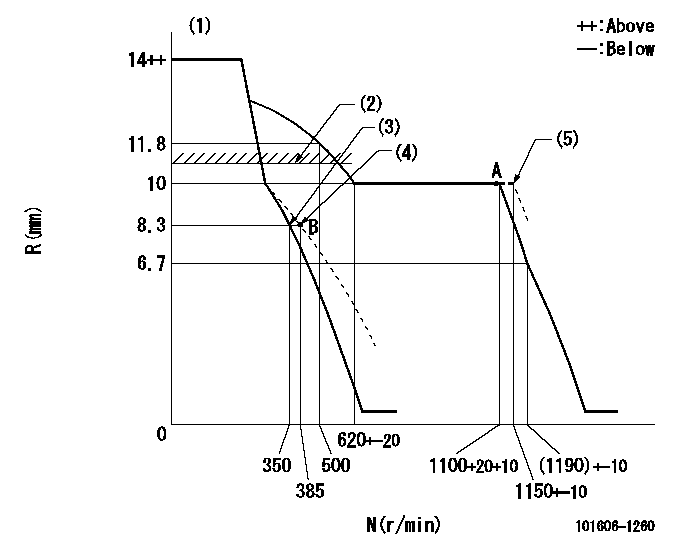
N:Pump speed
R:Rack position (mm)
(1)Notch fixed: K
(2)RACK LIMIT: RAL
(3)Main spring setting
(4)Set idle sub-spring
(5)At shipping
----------
K=15 RAL=11.5+-0.1mm
----------
----------
K=15 RAL=11.5+-0.1mm
----------
Speed control lever angle
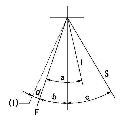
F:Full speed
I:Idle
S:Stop
(1)At shipping
----------
----------
a=24deg+-5deg b=10deg+-5deg c=32deg+-3deg d=(2deg)
----------
----------
a=24deg+-5deg b=10deg+-5deg c=32deg+-3deg d=(2deg)
Stop lever angle

N:Pump normal
S:Stop the pump.
----------
----------
a=26deg+-5deg b=53deg+-5deg
----------
----------
a=26deg+-5deg b=53deg+-5deg
Timing setting

(1)Pump vertical direction
(2)Position of timer's tooth at No 1 cylinder's beginning of injection
(3)B.T.D.C.: aa
(4)-
----------
aa=19deg
----------
a=(2deg)
----------
aa=19deg
----------
a=(2deg)
Information:
You must read and understand the warnings and instructions contained in the Safety section of this manual before performing any operation or maintenance procedures.Zinc Rods
Corrosion in sea water circuits can result in premature deterioration of system components, leaks, and possible cooling system contamination. The cause for the accelerated corrosion may be the lack of sacrificial zinc anodes (rods) in the sea water system.Zinc rods are inserted in the engine's sea water cooling system to help prevent the corrosive action of salt (sea) water. The reaction of the zinc to the sea water causes the rods to deteriorate, instead of more critical engine cooling system parts. Rapid deterioration of zinc rods may indicate the presence of stray electrical currents from improperly installed or grounded electrical attachments.The zinc rods must be inspected every 50 service hours and replaced when they have deteriorated.The location and number of zinc rods depends on the individual engine and the engine's attachments. Zinc rods are located in: the heat exchanger bonnet, the aftercooler lines, the raw/sea water heat exchanger bonnet, the raw/sea water pump, and the raw/sea water lines.Inspect
1. Remove all the zinc rod assemblies. The assembly plugs are painted red for easy identification. 2. Tap the zinc rods lightly with a hammer. If the rod has deteriorated, or flakes when tapped, install a new zinc rod.Replace
1. Unscrew or drill the old rod from the plug. Clean the plug.2. Apply 9S-3263 Compound to the shoulder of a new rod. Apply the compound only to the shoulder of the rod. Install the rod into the plug.3. Coat the external threads of the plug with 5P-3413 Pipe Sealant. Install the zinc rod assembly. Refer to the Torque Specifications in this manual.