Information injection-pump assembly
ZEXEL
101606-1171
1016061171
Rating:
Cross reference number
ZEXEL
101606-1171
1016061171
Zexel num
Bosch num
Firm num
Name
Calibration Data:
Adjustment conditions
Test oil
1404 Test oil ISO4113 or {SAEJ967d}
1404 Test oil ISO4113 or {SAEJ967d}
Test oil temperature
degC
40
40
45
Nozzle and nozzle holder
105780-8140
Bosch type code
EF8511/9A
Nozzle
105780-0000
Bosch type code
DN12SD12T
Nozzle holder
105780-2080
Bosch type code
EF8511/9
Opening pressure
MPa
17.2
Opening pressure
kgf/cm2
175
Injection pipe
Outer diameter - inner diameter - length (mm) mm 6-2-600
Outer diameter - inner diameter - length (mm) mm 6-2-600
Overflow valve
131424-5520
Overflow valve opening pressure
kPa
255
221
289
Overflow valve opening pressure
kgf/cm2
2.6
2.25
2.95
Tester oil delivery pressure
kPa
157
157
157
Tester oil delivery pressure
kgf/cm2
1.6
1.6
1.6
Direction of rotation (viewed from drive side)
Left L
Left L
Injection timing adjustment
Direction of rotation (viewed from drive side)
Left L
Left L
Injection order
1-5-3-6-
2-4
Pre-stroke
mm
3.6
3.55
3.65
Beginning of injection position
Governor side NO.1
Governor side NO.1
Difference between angles 1
Cal 1-5 deg. 60 59.5 60.5
Cal 1-5 deg. 60 59.5 60.5
Difference between angles 2
Cal 1-3 deg. 120 119.5 120.5
Cal 1-3 deg. 120 119.5 120.5
Difference between angles 3
Cal 1-6 deg. 180 179.5 180.5
Cal 1-6 deg. 180 179.5 180.5
Difference between angles 4
Cyl.1-2 deg. 240 239.5 240.5
Cyl.1-2 deg. 240 239.5 240.5
Difference between angles 5
Cal 1-4 deg. 300 299.5 300.5
Cal 1-4 deg. 300 299.5 300.5
Injection quantity adjustment
Adjusting point
-
Rack position
11
Pump speed
r/min
850
850
850
Each cylinder's injection qty
mm3/st.
60
58.1
61.9
Basic
*
Fixing the rack
*
Standard for adjustment of the maximum variation between cylinders
*
Injection quantity adjustment_02
Adjusting point
-
Rack position
10+-0.5
Pump speed
r/min
275
275
275
Each cylinder's injection qty
mm3/st.
10
8.9
11.1
Fixing the rack
*
Standard for adjustment of the maximum variation between cylinders
*
Remarks
Adjust only variation between cylinders; adjust governor according to governor specifications.
Adjust only variation between cylinders; adjust governor according to governor specifications.
Injection quantity adjustment_03
Adjusting point
A
Rack position
R1(11)
Pump speed
r/min
850
850
850
Average injection quantity
mm3/st.
60
59
61
Basic
*
Fixing the lever
*
Injection quantity adjustment_04
Adjusting point
B
Rack position
R1+0.6
Pump speed
r/min
1450
1450
1450
Average injection quantity
mm3/st.
80.5
78.5
82.5
Fixing the lever
*
Injection quantity adjustment_05
Adjusting point
I
Rack position
-
Pump speed
r/min
100
100
100
Average injection quantity
mm3/st.
80
75
85
Fixing the lever
*
Rack limit
*
Timer adjustment
Pump speed
r/min
1250--
Advance angle
deg.
0
0
0
Remarks
Start
Start
Timer adjustment_02
Pump speed
r/min
1200
Advance angle
deg.
0.5
Timer adjustment_03
Pump speed
r/min
1350
Advance angle
deg.
2.4
1.9
2.9
Timer adjustment_04
Pump speed
r/min
1500
Advance angle
deg.
5
4.5
5.5
Remarks
Finish
Finish
Test data Ex:
Governor adjustment
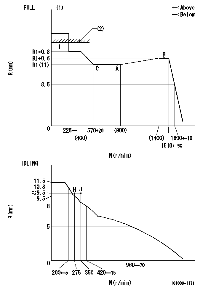
N:Pump speed
R:Rack position (mm)
(1)Torque cam stamping: T1
(2)RACK LIMIT
----------
T1=C69
----------
----------
T1=C69
----------
Speed control lever angle

F:Full speed
I:Idle
(1)Use the hole at R = aa
(2)Stopper bolt set position 'H'
----------
aa=40mm
----------
a=18.5deg+-5deg b=(42deg)+-3deg
----------
aa=40mm
----------
a=18.5deg+-5deg b=(42deg)+-3deg
Stop lever angle

N:Engine manufacturer's normal use
S:Stop the pump.
(1)Set the stopper bolt at speed = rated point and rack position = aa (non-injection rack position). Confirm non-injection.
(2)After setting the stopper bolt , confirm non-injection at pump speed bb. Rack position = cc (non-injection rack position).
(3)Rack position = approximately dd
(4)Free (at shipping)
----------
aa=7mm bb=275r/min cc=8mm dd=15mm
----------
a=38deg+-5deg b=(26.5deg) c=12.5deg+-3deg
----------
aa=7mm bb=275r/min cc=8mm dd=15mm
----------
a=38deg+-5deg b=(26.5deg) c=12.5deg+-3deg
0000001501 MICRO SWITCH
Adjustment of the micro-switch
Adjust the bolt to obtain the following lever position when the micro-switch is ON.
(1)Speed N1
(2)Rack position Ra
----------
N1=400+-5r/min Ra=9.2mm
----------
----------
N1=400+-5r/min Ra=9.2mm
----------
Timing setting

(1)Pump vertical direction
(2)Position of timer's tooth at No 1 cylinder's beginning of injection
(3)B.T.D.C.: aa
(4)-
----------
aa=12deg
----------
a=(1deg)
----------
aa=12deg
----------
a=(1deg)
Information:
If the vessel cannot continue under its own power, it is recommended that the vessel be towed. The propeller of a vessel being towed will windmill through the water. Propeller rotation causes the propeller shaft to rotate. An extended period of propeller shaft rotation without proper lubrication will damage the marine transmission shaft bearings. If pressurized oil cannot be supplied to the marine transmission shaft bearings during towing, the propeller shaft must be secured to prevent propeller shaft rotation.
Most marine transmissions can be back driven (propeller wind milling with dead engine) under the following conditions, provided that vessel speed does not exceed normal maximum propulsion speed of the vessel. For intermittent back driving, such as:* Sailboat auxiliary (short trips)* Towing purse boats in seining operations1. Start the engine and operate the marine gear in neutral, at normal oil pressure, for a minimum of five minutes. Do this once every 24 hours.2. Maintain the marine transmission oil level the same for back driving as for normal propulsion, or keep level above FULL mark on dipstick.3. Make sure the marine transmission is in neutral while the craft is being towed. For continuous back driving, such as:* Sailboat auxiliary (long trips)* Towing to deliver a boat* Towing home a boat with engine trouble (long trip-more than a day)1. Operate in neutral with oil at normal oil pressure for a minimum of five minutes every 12 hours.2. Fill the marine gear with oil until the oil level touches the input shaft on the engine centerline.3. Make sure the marine transmission is in neutral while the craft is being towed.Securing the Propeller
Reverse wind milling can cause engine damage. The best way to prevent reverse wind milling is to secure the propeller. If possible, lock the propeller shaft to prevent rotation.After the propeller shaft has been secured, have the towing vessel travel at slow speed in order to minimize the wind milling force on the propeller. If the vessel is being towed and the marine transmission is allowed to windmill for long periods, the engine must be started and the marine transmission operated for five minutes every 12 hours to lubricate the propeller shaft bearings.There are several ways of preventing propeller shaft rotation. The correct method depends upon the turning force of the propeller, and the construction of the propeller shaft tunnel. Use the method best suited for the type of installation.Propeller Shaft Wrapping
1. On small vessels, wrap a heavy rope around the propeller shaft. The number of wraps needed will depend upon the mass of the propeller and propeller shaft.2. Secure the rope in the opposite direction of propeller shaft rotation.Securing the Companion Flange
1. Remove one or more bolts from the companion flange coupling. Bolt a chain to the companion flange. Wrap the chain several times around the propeller shaft.2. Secure the loose end of the chain at a right angle to the propeller shaft and in the opposite direction of propeller shaft rotation.