Information injection-pump assembly
ZEXEL
101606-1162
1016061162
MITSUBISHI
ME076018
me076018

Rating:
Service parts 101606-1162 INJECTION-PUMP ASSEMBLY:
1.
_
6.
COUPLING PLATE
7.
COUPLING PLATE
8.
_
9.
_
11.
Nozzle and Holder
ME035748
12.
Open Pre:MPa(Kqf/cm2)
21.6(220)

15.
NOZZLE SET
Include in #1:
101606-1162
as INJECTION-PUMP ASSEMBLY
Include in #2:
104746-6170
as _
Cross reference number
ZEXEL
101606-1162
1016061162
MITSUBISHI
ME076018
me076018
Zexel num
Bosch num
Firm num
Name
Calibration Data:
Adjustment conditions
Test oil
1404 Test oil ISO4113 or {SAEJ967d}
1404 Test oil ISO4113 or {SAEJ967d}
Test oil temperature
degC
40
40
45
Nozzle and nozzle holder
105780-8140
Bosch type code
EF8511/9A
Nozzle
105780-0000
Bosch type code
DN12SD12T
Nozzle holder
105780-2080
Bosch type code
EF8511/9
Opening pressure
MPa
17.2
Opening pressure
kgf/cm2
175
Injection pipe
Outer diameter - inner diameter - length (mm) mm 6-2-600
Outer diameter - inner diameter - length (mm) mm 6-2-600
Overflow valve
131424-5520
Overflow valve opening pressure
kPa
255
221
289
Overflow valve opening pressure
kgf/cm2
2.6
2.25
2.95
Tester oil delivery pressure
kPa
157
157
157
Tester oil delivery pressure
kgf/cm2
1.6
1.6
1.6
Direction of rotation (viewed from drive side)
Left L
Left L
Injection timing adjustment
Direction of rotation (viewed from drive side)
Left L
Left L
Injection order
1-5-3-6-
2-4
Pre-stroke
mm
3.6
3.55
3.65
Beginning of injection position
Governor side NO.1
Governor side NO.1
Difference between angles 1
Cal 1-5 deg. 60 59.5 60.5
Cal 1-5 deg. 60 59.5 60.5
Difference between angles 2
Cal 1-3 deg. 120 119.5 120.5
Cal 1-3 deg. 120 119.5 120.5
Difference between angles 3
Cal 1-6 deg. 180 179.5 180.5
Cal 1-6 deg. 180 179.5 180.5
Difference between angles 4
Cyl.1-2 deg. 240 239.5 240.5
Cyl.1-2 deg. 240 239.5 240.5
Difference between angles 5
Cal 1-4 deg. 300 299.5 300.5
Cal 1-4 deg. 300 299.5 300.5
Injection quantity adjustment
Adjusting point
-
Rack position
11.1
Pump speed
r/min
850
850
850
Each cylinder's injection qty
mm3/st.
69
66.9
71.1
Basic
*
Fixing the rack
*
Standard for adjustment of the maximum variation between cylinders
*
Injection quantity adjustment_02
Adjusting point
H
Rack position
9.9+-0.5
Pump speed
r/min
275
275
275
Each cylinder's injection qty
mm3/st.
9.2
8.1
10.3
Fixing the rack
*
Standard for adjustment of the maximum variation between cylinders
*
Injection quantity adjustment_03
Adjusting point
A
Rack position
R1(11.1)
Pump speed
r/min
850
850
850
Average injection quantity
mm3/st.
69
68
70
Basic
*
Fixing the lever
*
Injection quantity adjustment_04
Adjusting point
B
Rack position
R1+0.35
Pump speed
r/min
1450
1450
1450
Average injection quantity
mm3/st.
82.5
78.5
86.5
Fixing the lever
*
Injection quantity adjustment_05
Adjusting point
C
Rack position
R1-0.2
Pump speed
r/min
600
600
600
Average injection quantity
mm3/st.
47.6
43.6
51.6
Fixing the lever
*
Injection quantity adjustment_06
Adjusting point
I
Rack position
-
Pump speed
r/min
100
100
100
Average injection quantity
mm3/st.
80
75
85
Fixing the lever
*
Rack limit
*
Timer adjustment
Pump speed
r/min
1250--
Advance angle
deg.
0
0
0
Remarks
Start
Start
Timer adjustment_02
Pump speed
r/min
1200
Advance angle
deg.
0.5
Timer adjustment_03
Pump speed
r/min
1350
Advance angle
deg.
2.4
1.9
2.9
Timer adjustment_04
Pump speed
r/min
1500
Advance angle
deg.
5
4.5
5.5
Remarks
Finish
Finish
Test data Ex:
Governor adjustment
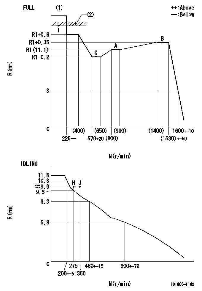
N:Pump speed
R:Rack position (mm)
(1)Torque cam stamping: T1
(2)RACK LIMIT
----------
T1=C98
----------
----------
T1=C98
----------
Speed control lever angle

F:Full speed
I:Idle
(1)Stopper bolt set position 'H'
----------
----------
a=10deg+-5deg b=(46deg)+-3deg
----------
----------
a=10deg+-5deg b=(46deg)+-3deg
Stop lever angle

N:Engine manufacturer's normal use
S:Stop the pump.
(1)At the rated pump speed and rack position aa, set the stopper bolt. (Confirm that there is no injection.)
(2)After setting the stopper bolt , confirm non-injection at pump speed bb. Rack position = cc (non-injection rack position).
(3)Rack position = approximately dd
(4)Free (at shipping)
----------
aa=7.1mm bb=275r/min cc=8.8mm dd=15mm
----------
a=38deg+-5deg b=(26.5deg) c=12.5deg+-3deg
----------
aa=7.1mm bb=275r/min cc=8.8mm dd=15mm
----------
a=38deg+-5deg b=(26.5deg) c=12.5deg+-3deg
0000001501 MICRO SWITCH
Adjustment of the micro-switch
Adjust the bolt to obtain the following lever position when the micro-switch is ON.
(1)Speed N1
(2)Rack position Ra
----------
N1=400+-5r/min Ra=9.7mm
----------
----------
N1=400+-5r/min Ra=9.7mm
----------
Timing setting

(1)Pump vertical direction
(2)Position of timer's tooth at No 1 cylinder's beginning of injection
(3)B.T.D.C.: aa
(4)-
----------
aa=12deg
----------
a=(1deg)
----------
aa=12deg
----------
a=(1deg)
Information:
Stopping the engine immediately after it has been working under load can result in overheating and accelerated wear of the engine components. Allow the engine to engine cool down before stopping. Avoiding hot engine shutdowns will maximize turbocharger shaft and bearing life.
Emergency Stopping
Emergency shutoff controls are for EMERGENCY use ONLY. DO NOT use emergency shutoff devices or controls for normal stopping procedure.
Make sure that any external system components that have been operating to support engine operation are secured after any stop.Emergency Stop Button
Emergency stop button, mounted on a junction box.Emergency stops may be made by pushing the Emergency Stop Button located on the junction box (if equipped). Both the button and the air inlet shutoff (if equipped) require resetting before the engine will start.Air Shutoff (If Equipped)
Some engines are equipped with an air shutoff, located between the aftercooler and the turbocharger. If equipped with an air shutoff lever, move the lever to the OFF position.Manual Stop Procedure
Stopping the engine immediately after it has been working under load, can result in overheating and accelerated wear of the engine components. Follow the stopping procedure, outlined below, to allow the engine to cool. Excessive temperatures in the turbocharger center housing will cause oil coking problems. Shutting the engine off without a cool down period does not allow the coolant temperature to stabilize, and may result in exhaust manifold cracking or leaking. Follow the stopping procedure outlined below to allow the engine to cool before shut down.
There may be several ways to shut off your engine. Make sure the shutoff procedures are understood. Use the following general guidelines for stopping the engine.1. Reduce engine speed to low idle.2. Shift into NEUTRAL.3. If the engine has been operated at low loads, run the engine at LOW IDLE for 30 seconds before stopping.If the engine has been operated at high load, increase engine speed to no more than 1/2 rated speed for three to five minutes to reduce and stabilize internal engine coolant and oil temperatures. Then reduce the engine speed to low idle before stopping.4. Check the marine transmission oil level while the engine is idling. Refer to the marine transmission OEM literature for lubrication maintenance recommendations.5. Follow your vessel's OEM instructions for stopping the engine with the pilot controls.A manual shutoff shaft is provided to override the governor control. The shaft can be used to move the fuel control linkage to the FUEL OFF position. The engine may be stopped by using the shaft and the mechanical governor control (if equipped).
Typical mechanical governor control.Move the mechanical governor control to the FUEL OFF position. Hold the control at the FUEL OFF position until the engine stops.After Stopping the Engine
Check the crankcase oil level. Maintain the oil level between the ADD and FULL marks on the dipstick.Repair any leaks, perform minor adjustments, tighten loose bolts, etc.Note the service hour meter reading. Perform periodic maintenance as instructed in the Maintenance Schedule.Fill the fuel tank to prevent accumulation of moisture in the fuel. Do not overfill.
Only