Information injection-pump assembly
ZEXEL
101606-1161
1016061161
Rating:
Cross reference number
ZEXEL
101606-1161
1016061161
Zexel num
Bosch num
Firm num
Name
Calibration Data:
Adjustment conditions
Test oil
1404 Test oil ISO4113 or {SAEJ967d}
1404 Test oil ISO4113 or {SAEJ967d}
Test oil temperature
degC
40
40
45
Nozzle and nozzle holder
105780-8140
Bosch type code
EF8511/9A
Nozzle
105780-0000
Bosch type code
DN12SD12T
Nozzle holder
105780-2080
Bosch type code
EF8511/9
Opening pressure
MPa
17.2
Opening pressure
kgf/cm2
175
Injection pipe
Outer diameter - inner diameter - length (mm) mm 6-2-600
Outer diameter - inner diameter - length (mm) mm 6-2-600
Overflow valve
131424-5520
Overflow valve opening pressure
kPa
255
221
289
Overflow valve opening pressure
kgf/cm2
2.6
2.25
2.95
Tester oil delivery pressure
kPa
157
157
157
Tester oil delivery pressure
kgf/cm2
1.6
1.6
1.6
Direction of rotation (viewed from drive side)
Left L
Left L
Injection timing adjustment
Direction of rotation (viewed from drive side)
Left L
Left L
Injection order
1-5-3-6-
2-4
Pre-stroke
mm
3.6
3.55
3.65
Beginning of injection position
Governor side NO.1
Governor side NO.1
Difference between angles 1
Cal 1-5 deg. 60 59.5 60.5
Cal 1-5 deg. 60 59.5 60.5
Difference between angles 2
Cal 1-3 deg. 120 119.5 120.5
Cal 1-3 deg. 120 119.5 120.5
Difference between angles 3
Cal 1-6 deg. 180 179.5 180.5
Cal 1-6 deg. 180 179.5 180.5
Difference between angles 4
Cyl.1-2 deg. 240 239.5 240.5
Cyl.1-2 deg. 240 239.5 240.5
Difference between angles 5
Cal 1-4 deg. 300 299.5 300.5
Cal 1-4 deg. 300 299.5 300.5
Injection quantity adjustment
Adjusting point
-
Rack position
10.8
Pump speed
r/min
850
850
850
Each cylinder's injection qty
mm3/st.
60
58.1
61.9
Basic
*
Fixing the rack
*
Standard for adjustment of the maximum variation between cylinders
*
Injection quantity adjustment_02
Adjusting point
H
Rack position
9.5+-0.5
Pump speed
r/min
275
275
275
Each cylinder's injection qty
mm3/st.
9.3
8.2
10.4
Fixing the rack
*
Standard for adjustment of the maximum variation between cylinders
*
Injection quantity adjustment_03
Adjusting point
A
Rack position
R1(10.8)
Pump speed
r/min
850
850
850
Average injection quantity
mm3/st.
60
59
61
Basic
*
Fixing the lever
*
Injection quantity adjustment_04
Adjusting point
B
Rack position
R1+0.6
Pump speed
r/min
1450
1450
1450
Average injection quantity
mm3/st.
80.5
78.5
82.5
Fixing the lever
*
Injection quantity adjustment_05
Adjusting point
I
Rack position
-
Pump speed
r/min
100
100
100
Average injection quantity
mm3/st.
80
75
85
Fixing the lever
*
Rack limit
*
Timer adjustment
Pump speed
r/min
1250--
Advance angle
deg.
0
0
0
Remarks
Start
Start
Timer adjustment_02
Pump speed
r/min
1200
Advance angle
deg.
0.5
Timer adjustment_03
Pump speed
r/min
1350
Advance angle
deg.
2.4
1.9
2.9
Timer adjustment_04
Pump speed
r/min
1500
Advance angle
deg.
5
4.5
5.5
Remarks
Finish
Finish
Test data Ex:
Governor adjustment
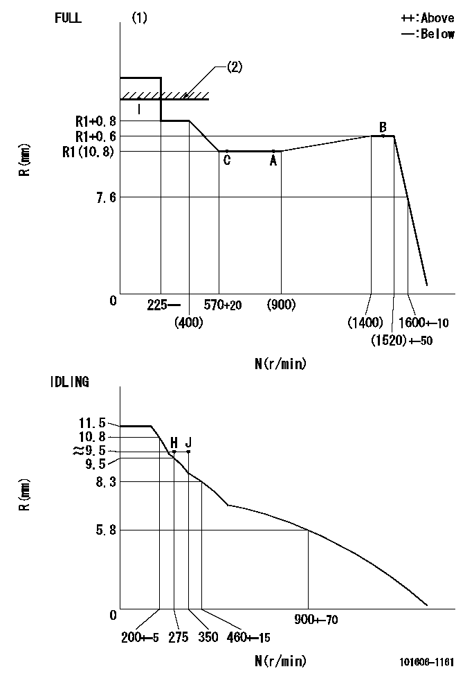
N:Pump speed
R:Rack position (mm)
(1)Torque cam stamping: T1
(2)RACK LIMIT
----------
T1=C70
----------
----------
T1=C70
----------
Speed control lever angle

F:Full speed
I:Idle
(1)Stopper bolt set position 'H'
----------
----------
a=10deg+-5deg b=(46deg)+-3deg
----------
----------
a=10deg+-5deg b=(46deg)+-3deg
Stop lever angle

N:Engine manufacturer's normal use
S:Stop the pump.
(1)Set the stopper bolt at speed = rated point and rack position = aa (non-injection rack position). Confirm non-injection.
(2)After setting the stopper bolt , confirm non-injection at pump speed bb. Rack position = cc (non-injection rack position).
(3)Rack position = approximately dd
(4)Free (at shipping)
----------
aa=7.1mm bb=275r/min cc=8.8mm dd=15mm
----------
a=38deg+-5deg b=(26.5deg) c=12.5deg+-3deg
----------
aa=7.1mm bb=275r/min cc=8.8mm dd=15mm
----------
a=38deg+-5deg b=(26.5deg) c=12.5deg+-3deg
0000001501 MICRO SWITCH
Adjustment of the micro-switch
Adjust the bolt to obtain the following lever position when the micro-switch is ON.
(1)Speed N1
(2)Rack position Ra
----------
N1=400+-5r/min Ra=9.2mm
----------
----------
N1=400+-5r/min Ra=9.2mm
----------
Timing setting

(1)Pump vertical direction
(2)Position of timer's tooth at No 1 cylinder's beginning of injection
(3)B.T.D.C.: aa
(4)-
----------
aa=12deg
----------
a=(1deg)
----------
aa=12deg
----------
a=(1deg)
Information:
Raw/Sea Water Pump Failure
The raw/sea water pump circulates sea or fresh water through the engine jacket water heat exchanger. If the raw/sea water pump should fail, follow the procedure below to continue engine operation.
Shut off valve-normally closed (1), emergency raw/sea water pump (2), emergency raw/sea water inlet (3), inlet valve-normally closed (4), emergency raw/sea water strainers (5), normal operation raw/sea water strainers (6), normal operation raw/sea water inlet (7), inlet valve-normally open (8), raw/sea water pump (9), jacket water heat exchanger (10), raw/sea water outlet (11), and aftercooler (12).1. Stop the engine. If the shaft bearing has failed, the pump does NOT need to be removed.2. Close inlet valve (8) to raw/sea water strainers (6) and raw/sea water pump (9).3. Open inlet valve (4) to emergency raw/sea water pump (2). Start and prime the pump.4. Start the engine. Engage the marine gear and continue operation at normal speed.Engine Lube Oil Pump Failure
If the engine lube oil pump fails, the oil pressure will drop and the engine jacket water temperature gauge reading will be above normal. The applicable engine shutoff controls (if equipped) will stop the engine. Refer to the following procedure to use the emergency lube oil pump.1. Place the marine gear in the NEUTRAL position. Stop the engine (if the engine is still running).2. Measure the engine oil level. Ensure the oil level is between the ADD and FULL marks on the dipstick. Add oil if necessary.3. Reset the oil pressure shutoff control (if equipped). Be sure that the oil pressure shutoff control RESET is in the RUN position to enable engine starting.4. Start the emergency standby lube oil pump. Observe the oil pressure gauge5. Start the engine. Engage the marine gear and operate the vessel at normal speed.Turbocharger Failure
Air cleaner (1), turbocharger air inlet hose (2), compressor (3), clamp (4), cartridge (5), turbine housing (6), oil supply line (7), aftercooler air inlet hose (8), and oil drain line (9).1. Remove air cleaner (1) and turbocharger air inlet hose (2).2. Remove oil supply line (7) from the top of cartridge (5). Remove oil supply line (7) from the cylinder block. Plug the oil supply opening in the cylinder block.3. Remove oil drain line (9) from the bottom of cartridge (5). Remove oil drain line (9) from the flywheel housing. Plug the oil drain opening in the flyheel housing.4. Remove the bolts from the flange to aftercooler air inlet hose (8).5. Remove clamp (4) while supporting compressor (3) and aftercooler air inlet hose (8). Remove aftercooler air inlet hose (8), compressor (3) and cartridge (5) as a unit.
DO NOT allow exhaust gas to discharge into engine room. Vent the exhaust to the outside and be sure venting systems are correctly installed and operating. Diesel engine exhaust contains products of combustion which may be harmful to your health.
6. Provide some means of attaching a flat steel against the opening in turbine housing (6) where cartridge (5) was removed. The plate must be large enough to completely cover the opening.