Information injection-pump assembly
ZEXEL
101606-1160
1016061160

Rating:
Cross reference number
ZEXEL
101606-1160
1016061160
Zexel num
Bosch num
Firm num
Name
Calibration Data:
Adjustment conditions
Test oil
1404 Test oil ISO4113 or {SAEJ967d}
1404 Test oil ISO4113 or {SAEJ967d}
Test oil temperature
degC
40
40
45
Nozzle and nozzle holder
105780-8140
Bosch type code
EF8511/9A
Nozzle
105780-0000
Bosch type code
DN12SD12T
Nozzle holder
105780-2080
Bosch type code
EF8511/9
Opening pressure
MPa
17.2
Opening pressure
kgf/cm2
175
Injection pipe
Outer diameter - inner diameter - length (mm) mm 6-2-600
Outer diameter - inner diameter - length (mm) mm 6-2-600
Overflow valve
131424-5520
Overflow valve opening pressure
kPa
255
221
289
Overflow valve opening pressure
kgf/cm2
2.6
2.25
2.95
Tester oil delivery pressure
kPa
157
157
157
Tester oil delivery pressure
kgf/cm2
1.6
1.6
1.6
Direction of rotation (viewed from drive side)
Left L
Left L
Injection timing adjustment
Direction of rotation (viewed from drive side)
Left L
Left L
Injection order
1-5-3-6-
2-4
Pre-stroke
mm
3.6
3.55
3.65
Beginning of injection position
Governor side NO.1
Governor side NO.1
Difference between angles 1
Cal 1-5 deg. 60 59.5 60.5
Cal 1-5 deg. 60 59.5 60.5
Difference between angles 2
Cal 1-3 deg. 120 119.5 120.5
Cal 1-3 deg. 120 119.5 120.5
Difference between angles 3
Cal 1-6 deg. 180 179.5 180.5
Cal 1-6 deg. 180 179.5 180.5
Difference between angles 4
Cyl.1-2 deg. 240 239.5 240.5
Cyl.1-2 deg. 240 239.5 240.5
Difference between angles 5
Cal 1-4 deg. 300 299.5 300.5
Cal 1-4 deg. 300 299.5 300.5
Injection quantity adjustment
Adjusting point
-
Rack position
10.8
Pump speed
r/min
850
850
850
Each cylinder's injection qty
mm3/st.
60
58.1
61.9
Basic
*
Fixing the rack
*
Standard for adjustment of the maximum variation between cylinders
*
Injection quantity adjustment_02
Adjusting point
H
Rack position
9.5+-0.5
Pump speed
r/min
275
275
275
Each cylinder's injection qty
mm3/st.
9.3
8.2
10.4
Fixing the rack
*
Standard for adjustment of the maximum variation between cylinders
*
Injection quantity adjustment_03
Adjusting point
A
Rack position
R1(10.8)
Pump speed
r/min
850
850
850
Average injection quantity
mm3/st.
60
59
61
Basic
*
Fixing the lever
*
Injection quantity adjustment_04
Adjusting point
B
Rack position
R1+0.6
Pump speed
r/min
1450
1450
1450
Average injection quantity
mm3/st.
80.5
78.5
82.5
Fixing the lever
*
Injection quantity adjustment_05
Adjusting point
I
Rack position
-
Pump speed
r/min
100
100
100
Average injection quantity
mm3/st.
80
75
85
Fixing the lever
*
Rack limit
*
Timer adjustment
Pump speed
r/min
1250--
Advance angle
deg.
0
0
0
Remarks
Start
Start
Timer adjustment_02
Pump speed
r/min
1200
Advance angle
deg.
0.5
Timer adjustment_03
Pump speed
r/min
1350
Advance angle
deg.
2.4
1.9
2.9
Timer adjustment_04
Pump speed
r/min
1500
Advance angle
deg.
5
4.5
5.5
Remarks
Finish
Finish
Test data Ex:
Governor adjustment
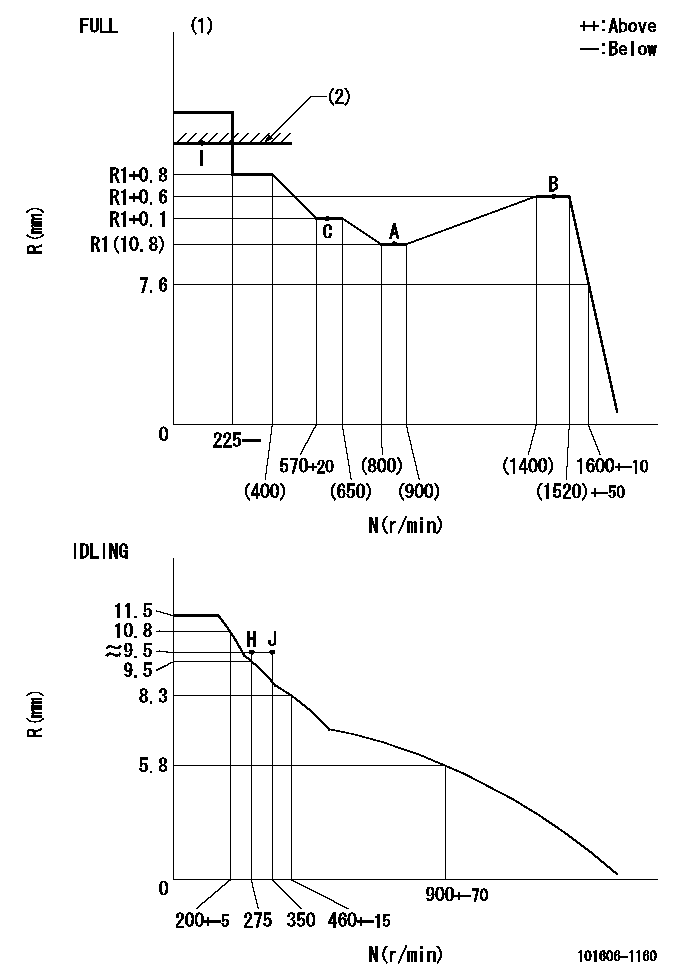
N:Pump speed
R:Rack position (mm)
(1)Torque cam stamping: T1
(2)RACK LIMIT
----------
T1=C19
----------
----------
T1=C19
----------
Speed control lever angle

F:Full speed
I:Idle
(1)Stopper bolt set position 'H'
----------
----------
a=10deg+-5deg b=(46deg)+-3deg
----------
----------
a=10deg+-5deg b=(46deg)+-3deg
Stop lever angle

N:Engine manufacturer's normal use
S:Stop the pump.
(1)Set the stopper bolt at speed = rated point and rack position = aa (non-injection rack position). Confirm non-injection.
(2)After setting the stopper bolt , confirm non-injection at pump speed bb. Rack position = cc (non-injection rack position).
(3)Rack position = approximately dd
(4)Free (at shipping)
----------
aa=7.1mm bb=275r/min cc=8.8mm dd=15mm
----------
a=38deg+-5deg b=(26.5deg) c=12.5deg+-3deg
----------
aa=7.1mm bb=275r/min cc=8.8mm dd=15mm
----------
a=38deg+-5deg b=(26.5deg) c=12.5deg+-3deg
0000001501 MICRO SWITCH
Adjustment of the micro-switch
Adjust the bolt to obtain the following lever position when the micro-switch is ON.
(1)Speed N1
(2)Rack position Ra
----------
N1=400+-5r/min Ra=9.2mm
----------
----------
N1=400+-5r/min Ra=9.2mm
----------
Timing setting

(1)Pump vertical direction
(2)Position of timer's tooth at No 1 cylinder's beginning of injection
(3)B.T.D.C.: aa
(4)-
----------
aa=12deg
----------
a=(1deg)
----------
aa=12deg
----------
a=(1deg)
Information:
When using an external electrical source to start your engine: turn the START switch off, remove the key, and turn off all electrical accessories before attaching cables.When using jumper cables always connect the POSITIVE (+) cable to the POSITIVE (+) terminal of the battery connected to the starter solenoid. Connect the NEGATIVE (-) cable from the external source to the starter NEGATIVE (-) terminal. If not equipped with a starter NEGATIVE terminal, connect to the engine block.Do not reverse the battery cables. The alternator can be damaged. Attach the ground cable last and remove first.
1. Connect one end of the cable to the POSITIVE (+) terminal of the battery being started. Connect the other end to the POSITIVE (+) terminal of the power source.2. Connect one end of the other cable to the NEGATIVE (-) terminal of the power source. Connect the other end to the starter NEGATIVE (-) terminal or to the engine block. This prevents potential sparks from igniting combustible gases produced by some batteries.3. Start the engine.4. After the engine starts, disconnect the cable from the starter NEGATIVE (-) terminal or engine block. Disconnect the other end from the NEGATIVE (-) terminal of the power source.5. Disconnect the cable from the POSITIVE (+) terminal of the battery on the engine being started. Disconnect the cable from the POSITIVE (+) terminal of the power source.Glow Plugs
Precombustion Chamber Engines
Never use the glow plugs when the engine is warm and running.
HEAT/START switch: HEAT (1), OFF (2), and START (3) positions.1. Push the HEAT/START switch and turn the switch to the HEAT position. Maintain the switch in the HEAT position for the appropriate time shown in the Starting Aid Chart.2. Turn the HEAT/START switch to the START position.3. If the engine runs rough after starting, turn the HEAT/START switch to the HEAT position. Maintain the position until the engine runs smoothly. Air Starting
For good life of the air starting motor, the air supply must be free of dirt and water. A lubricator must be used with the starting system. Use non detergent 10W engine oil for temperatures above 0°C (32°F). Use air tool oil for temperatures below 0°C (32°F).Older air starters are equipped with a lubricator bowl. Newer air starters are self-lubricating.1. Open and close the drain valve on the bottom of the air tank to drain condensation and oil carryover.2. Check the air supply pressure. The air starting motor requires a minimum of 690 kPa (100 psi) air pressure. The maximum air pressure must not exceed 1034 kPa (150 psi).
Air starter: air valve (1) and lubricator bowl (2)3. Check the oil level in the lubricator bowl (if equipped, 2). Keep the bowl at least half full and add lubricant if necessary.4. Push the air valve (1) or the engine start button to crank the engine. Release the valve or button as soon as the engine starts.Cold Weather Starting Aids
Personal injury or death can result from using ether.Personal injury or property damage can result from alcohol or starting fluids.