Information injection-pump assembly
ZEXEL
101606-1151
1016061151

Rating:
Cross reference number
ZEXEL
101606-1151
1016061151
Zexel num
Bosch num
Firm num
Name
Calibration Data:
Adjustment conditions
Test oil
1404 Test oil ISO4113 or {SAEJ967d}
1404 Test oil ISO4113 or {SAEJ967d}
Test oil temperature
degC
40
40
45
Nozzle and nozzle holder
105780-8140
Bosch type code
EF8511/9A
Nozzle
105780-0000
Bosch type code
DN12SD12T
Nozzle holder
105780-2080
Bosch type code
EF8511/9
Opening pressure
MPa
17.2
Opening pressure
kgf/cm2
175
Injection pipe
Outer diameter - inner diameter - length (mm) mm 6-2-600
Outer diameter - inner diameter - length (mm) mm 6-2-600
Overflow valve
131424-5520
Overflow valve opening pressure
kPa
255
221
289
Overflow valve opening pressure
kgf/cm2
2.6
2.25
2.95
Tester oil delivery pressure
kPa
157
157
157
Tester oil delivery pressure
kgf/cm2
1.6
1.6
1.6
Direction of rotation (viewed from drive side)
Left L
Left L
Injection timing adjustment
Direction of rotation (viewed from drive side)
Left L
Left L
Injection order
1-5-3-6-
2-4
Pre-stroke
mm
3.6
3.55
3.65
Beginning of injection position
Governor side NO.1
Governor side NO.1
Difference between angles 1
Cal 1-5 deg. 60 59.5 60.5
Cal 1-5 deg. 60 59.5 60.5
Difference between angles 2
Cal 1-3 deg. 120 119.5 120.5
Cal 1-3 deg. 120 119.5 120.5
Difference between angles 3
Cal 1-6 deg. 180 179.5 180.5
Cal 1-6 deg. 180 179.5 180.5
Difference between angles 4
Cyl.1-2 deg. 240 239.5 240.5
Cyl.1-2 deg. 240 239.5 240.5
Difference between angles 5
Cal 1-4 deg. 300 299.5 300.5
Cal 1-4 deg. 300 299.5 300.5
Injection quantity adjustment
Adjusting point
-
Rack position
11
Pump speed
r/min
850
850
850
Each cylinder's injection qty
mm3/st.
60
58.1
61.9
Basic
*
Fixing the rack
*
Standard for adjustment of the maximum variation between cylinders
*
Injection quantity adjustment_02
Adjusting point
-
Rack position
10+-0.5
Pump speed
r/min
275
275
275
Each cylinder's injection qty
mm3/st.
10
8.9
11.1
Fixing the rack
*
Standard for adjustment of the maximum variation between cylinders
*
Remarks
Adjust only variation between cylinders; adjust governor according to governor specifications.
Adjust only variation between cylinders; adjust governor according to governor specifications.
Injection quantity adjustment_03
Adjusting point
A
Rack position
R1(11)
Pump speed
r/min
850
850
850
Average injection quantity
mm3/st.
60
59
61
Basic
*
Fixing the lever
*
Injection quantity adjustment_04
Adjusting point
B
Rack position
R1+0.6
Pump speed
r/min
1450
1450
1450
Average injection quantity
mm3/st.
80.5
78.5
82.5
Fixing the lever
*
Injection quantity adjustment_05
Adjusting point
I
Rack position
-
Pump speed
r/min
100
100
100
Average injection quantity
mm3/st.
80
75
85
Fixing the lever
*
Rack limit
*
Timer adjustment
Pump speed
r/min
1250--
Advance angle
deg.
0
0
0
Remarks
Start
Start
Timer adjustment_02
Pump speed
r/min
1200
Advance angle
deg.
0.5
Timer adjustment_03
Pump speed
r/min
1350
Advance angle
deg.
2.4
1.9
2.9
Timer adjustment_04
Pump speed
r/min
1500
Advance angle
deg.
5
4.5
5.5
Remarks
Finish
Finish
Test data Ex:
Governor adjustment
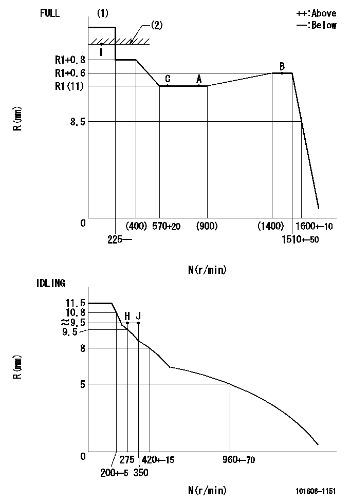
N:Pump speed
R:Rack position (mm)
(1)Torque cam stamping: T1
(2)RACK LIMIT
----------
T1=C69
----------
----------
T1=C69
----------
Speed control lever angle

F:Full speed
I:Idle
(1)Stopper bolt set position 'H'
----------
----------
a=18.5deg+-5deg b=(42deg)+-3deg
----------
----------
a=18.5deg+-5deg b=(42deg)+-3deg
Stop lever angle

N:Engine manufacturer's normal use
S:Stop the pump.
(1)At the rated pump speed and rack position aa, set the stopper bolt. (Confirm that there is no injection.)
(2)After setting the stopper bolt , confirm non-injection at pump speed bb. Rack position = cc (non-injection rack position).
(3)Rack position = approximately dd
(4)Free (at shipping)
----------
aa=7mm bb=275r/min cc=8mm dd=15mm
----------
a=38deg+-5deg b=(26.5deg) c=12.5deg+-3deg
----------
aa=7mm bb=275r/min cc=8mm dd=15mm
----------
a=38deg+-5deg b=(26.5deg) c=12.5deg+-3deg
0000001501 MICRO SWITCH
Adjustment of the micro-switch
Adjust the bolt to obtain the following lever position when the micro-switch is ON.
(1)Speed N1
(2)Rack position Ra
----------
N1=400+-5r/min Ra=9.2mm
----------
----------
N1=400+-5r/min Ra=9.2mm
----------
Timing setting

(1)Pump vertical direction
(2)Position of timer's tooth at No 1 cylinder's beginning of injection
(3)B.T.D.C.: aa
(4)-
----------
aa=12deg
----------
a=(1deg)
----------
aa=12deg
----------
a=(1deg)
Information:
Gauges provide indications of engine performance. Be sure they are in good working order. You can determine what is the "normal" operating range by observing the gauges over a period of time.Noticeable changes in gauge readings indicate potential gauge or engine problems. This also applies to gauge readings that have changed significantly, but are still within specifications. The cause of any sudden or significant change in gauge readings should be determined and corrected. Contact your Caterpillar dealer for assistance as needed. Oil Pressure - Indicates engine oil pressure. The oil pressure should be greatest after starting a cold engine. Oil pressure should read between 240 and 480 kPa (35 and 70 psi) when: the engine is running between 600 and 2100 rpm with SAE 10W30 oil, at an operating oil temperature of 105°C (220°F). A lower pressure is normal at low idling speed.If the oil pressure gauge reading fluctuates after the load is stable:1. Remove the load.2. Reduce engine speed to low idle.3. Check and maintain the oil level.
Engine damage can result if the engine is operated with no oil pressure gauge reading. If no pressure is indicated, stop the engine.
Engine Oil Temperature - Indicates engine oil temperature. The purpose of the oil is to lubricate all moving parts inside the engine, and to cool the pistons and bearings. The oil cooler transfers the heat in the oil to the engine jacket water.If the cooling system cannot remove the necessary heat from the water, the engine oil cannot be properly cooled. Higher than normal oil temperature indicates a heat problem has occurred in the lubrication and/or cooling system, and a problem can occur with cylinder heads, liners, pistons or bearings. Maximum oil temperature is 110°C (230°F).Jacket Water Temperature - Indicates engine coolant temperature. It should normally indicate from 79 to 99°C (175 to 210°F). Higher temperatures may occur under certain conditions. Maximum allowable temperature is 105°C (220°F) with the cooling system pressurized.If the engine is operating above normal range and steam becomes apparent:1. Reduce the load and reduce the engine rpm.2. Inspect the engine for cooling system for leaks.3. Determine if the engine must be shutdown immediately or if the engine can be cooled by reducing the load. Inlet Air Temperature - Indicates inlet manifold air temperature. As the inlet air increases in temperature, the air expands, less oxygen is available in the cylinders, and less power is developed. As a result, at full speed position with a full load, the engine may be overloaded. Maximum inlet manifold air temperature is:* 110°C (230°F) for DITA engines* 163°C (325°F) for DIT engines Exhaust Stack Temperature - Indicates exhaust gas temperature. Maximum exhaust temperature is approximately 575°C (1065°F). Fuel Level - Indicates fuel level in the fuel tank. The electrically operated fuel level gauge registers only when the START/STOP (ignition) switch is ON. Fuel Pressure - Indicates fuel pressure to the injection pump. The indicator should register in the NORMAL (green) range.If the indicator moves to the OUT position or