Information injection-pump assembly
ZEXEL
101606-1140
1016061140

Rating:
Cross reference number
ZEXEL
101606-1140
1016061140
Zexel num
Bosch num
Firm num
Name
Calibration Data:
Adjustment conditions
Test oil
1404 Test oil ISO4113 or {SAEJ967d}
1404 Test oil ISO4113 or {SAEJ967d}
Test oil temperature
degC
40
40
45
Nozzle and nozzle holder
105780-8140
Bosch type code
EF8511/9A
Nozzle
105780-0000
Bosch type code
DN12SD12T
Nozzle holder
105780-2080
Bosch type code
EF8511/9
Opening pressure
MPa
17.2
Opening pressure
kgf/cm2
175
Injection pipe
Outer diameter - inner diameter - length (mm) mm 6-2-600
Outer diameter - inner diameter - length (mm) mm 6-2-600
Overflow valve
131424-5520
Overflow valve opening pressure
kPa
255
221
289
Overflow valve opening pressure
kgf/cm2
2.6
2.25
2.95
Tester oil delivery pressure
kPa
157
157
157
Tester oil delivery pressure
kgf/cm2
1.6
1.6
1.6
Direction of rotation (viewed from drive side)
Left L
Left L
Injection timing adjustment
Direction of rotation (viewed from drive side)
Left L
Left L
Injection order
1-5-3-6-
2-4
Pre-stroke
mm
3.6
3.55
3.65
Beginning of injection position
Governor side NO.1
Governor side NO.1
Difference between angles 1
Cal 1-5 deg. 60 59.5 60.5
Cal 1-5 deg. 60 59.5 60.5
Difference between angles 2
Cal 1-3 deg. 120 119.5 120.5
Cal 1-3 deg. 120 119.5 120.5
Difference between angles 3
Cal 1-6 deg. 180 179.5 180.5
Cal 1-6 deg. 180 179.5 180.5
Difference between angles 4
Cyl.1-2 deg. 240 239.5 240.5
Cyl.1-2 deg. 240 239.5 240.5
Difference between angles 5
Cal 1-4 deg. 300 299.5 300.5
Cal 1-4 deg. 300 299.5 300.5
Injection quantity adjustment
Adjusting point
-
Rack position
11
Pump speed
r/min
850
850
850
Each cylinder's injection qty
mm3/st.
60
58.1
61.9
Basic
*
Fixing the rack
*
Standard for adjustment of the maximum variation between cylinders
*
Injection quantity adjustment_02
Adjusting point
-
Rack position
10+-0.5
Pump speed
r/min
275
275
275
Each cylinder's injection qty
mm3/st.
10
8.9
11.1
Fixing the rack
*
Standard for adjustment of the maximum variation between cylinders
*
Remarks
Adjust only variation between cylinders; adjust governor according to governor specifications.
Adjust only variation between cylinders; adjust governor according to governor specifications.
Injection quantity adjustment_03
Adjusting point
A
Rack position
R1(11)
Pump speed
r/min
850
850
850
Average injection quantity
mm3/st.
60
59
61
Basic
*
Fixing the lever
*
Injection quantity adjustment_04
Adjusting point
B
Rack position
R1+0.6
Pump speed
r/min
1450
1450
1450
Average injection quantity
mm3/st.
80.5
78.5
82.5
Fixing the lever
*
Injection quantity adjustment_05
Adjusting point
I
Rack position
-
Pump speed
r/min
100
100
100
Average injection quantity
mm3/st.
80
75
85
Fixing the lever
*
Rack limit
*
Timer adjustment
Pump speed
r/min
1250--
Advance angle
deg.
0
0
0
Remarks
Start
Start
Timer adjustment_02
Pump speed
r/min
1200
Advance angle
deg.
0.5
Timer adjustment_03
Pump speed
r/min
1350
Advance angle
deg.
2.4
1.9
2.9
Timer adjustment_04
Pump speed
r/min
1500
Advance angle
deg.
5
4.5
5.5
Remarks
Finish
Finish
Test data Ex:
Governor adjustment
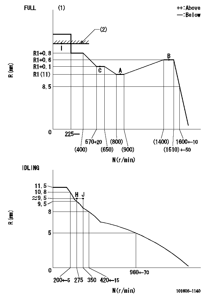
N:Pump speed
R:Rack position (mm)
(1)Torque cam stamping: T1
(2)RACK LIMIT
----------
T1=C14
----------
----------
T1=C14
----------
Speed control lever angle

F:Full speed
I:Idle
(1)Use the hole at R = aa
(2)Stopper bolt set position 'H'
----------
aa=40mm
----------
a=18.5deg+-5deg b=(42deg)+-3deg
----------
aa=40mm
----------
a=18.5deg+-5deg b=(42deg)+-3deg
Stop lever angle

N:Engine manufacturer's normal use
S:Stop the pump.
(1)Set the stopper bolt at speed = rated point and rack position = aa (non-injection rack position). Confirm non-injection.
(2)After setting the stopper bolt , confirm non-injection at pump speed bb. Rack position = cc (non-injection rack position).
(3)Rack position = approximately dd
(4)Free (at shipping)
----------
aa=(7)mm bb=275r/min cc=(8)mm dd=17.4mm
----------
a=38.5deg+-5deg b=(27deg) c=17deg+-5deg
----------
aa=(7)mm bb=275r/min cc=(8)mm dd=17.4mm
----------
a=38.5deg+-5deg b=(27deg) c=17deg+-5deg
0000001501 MICRO SWITCH
Adjustment of the micro-switch
Adjust the bolt to obtain the following lever position when the micro-switch is ON.
(1)Speed N1
(2)Rack position Ra
----------
N1=400+-5r/min Ra=9.2mm
----------
----------
N1=400+-5r/min Ra=9.2mm
----------
Timing setting

(1)Pump vertical direction
(2)Position of timer's tooth at No 1 cylinder's beginning of injection
(3)B.T.D.C.: aa
(4)-
----------
aa=12deg
----------
a=(1deg)
----------
aa=12deg
----------
a=(1deg)
Information:
Rating Conditions
Unless otherwise specified, all ratings are based on SAE J1349 standard ambient conditions:* 100 kPa (29.6 inches of Hg) of pressure* 30 percent relative humidity, and* a temperature of 26°C (77°F)Ratings also apply at ISO8665, ISO3046/1, DIN6271, and BS5514 standard conditions.Power for diesel engines is based on:* API gravity of 35 at 15°C (60°F)* fuel LHV of 42,780 kJ/g (18390 Btu/lb) at 29°C (84°F)* fuel density of 839 g/L (7 lb/US gal)Ratings are gross output ratings- the total output capability of the engine equipped with standard accessories. Standard accessories include pumps for lubrication oil, fuel, and jacket water. The gross output, minus the power required to drive auxiliary components, equals the net power available for the external (flywheel) load. Typical auxiliary components include cooling fans, air compressors, and charging alternators.Rating Definitions
It is important to know how the vessel will be operating, so that the rating can match the operating profile. Additionally, proper rating selection is important so that customer perception of price/value is realized. In selecting a rating for a specific application, the most important consideration is time spent at full throttle. These rating definitions identify the percent of time at full throttle and corresponding times below rated rpm. A (Continuous): For heavy-duty service in ocean-going displacement hull vessels such as freighters, tugboats, bottom drag trawlers, and deep river towboats when the engine is operated at rated load and speed up to 100 percent of the time without interruption or load cycling. Typical use is 5000 to 8000 hours per year. B (Medium Duty): For displacement hull vessels such as mid-water trawlers, purse seiners, crew and supply boats, ferries, and towboats where locks, sandbars and curves dictate frequent slowing when engine load and speed are constant with some cycling. The engine may be operated up to 80 percent load factor and at rated load and speed for up to 80 percent of the duty cycle, or 10 hours out of every 12 hours. Typical use is 3000 to 5000 hours per year. C (Intermittent): For planing hull vessels such as ferries, fishing boats moving at higher speeds out and back (i.e. lobster, crayfish and tuna) offshore service boats, and also displacement hull yachts and short trip coastal freighters where engine load and speed are cyclical. The engine may be operated at up to 80 percent load factor and at rated load and speed for up to 50 percent of the duty cycle, or 6 hours out of every 12 hours. Typical use is 2000 to 4000 hours per year. D (Patrol Craft): For planning hull vessels such as offshore patrol boats, customs, police, and some fire and fishing boats. Also used for bow and stern thursters. The engine may be operated at up to 50 percent load factor and at rated load and speed for up to 16 percent of the duty cycle or 2 hours out of every 12 hours. Typical use is 1000 to 3000 hours per year. E (High Performance): For planning hull vessels