Information injection-pump assembly
ZEXEL
101606-1132
1016061132
MITSUBISHI
ME076012
me076012

Rating:
Cross reference number
ZEXEL
101606-1132
1016061132
MITSUBISHI
ME076012
me076012
Zexel num
Bosch num
Firm num
Name
101606-1132
ME076012 MITSUBISHI
INJECTION-PUMP ASSEMBLY
6D15 * K
6D15 * K
Calibration Data:
Adjustment conditions
Test oil
1404 Test oil ISO4113 or {SAEJ967d}
1404 Test oil ISO4113 or {SAEJ967d}
Test oil temperature
degC
40
40
45
Nozzle and nozzle holder
105780-8140
Bosch type code
EF8511/9A
Nozzle
105780-0000
Bosch type code
DN12SD12T
Nozzle holder
105780-2080
Bosch type code
EF8511/9
Opening pressure
MPa
17.2
Opening pressure
kgf/cm2
175
Injection pipe
Outer diameter - inner diameter - length (mm) mm 6-2-600
Outer diameter - inner diameter - length (mm) mm 6-2-600
Overflow valve
131424-5520
Overflow valve opening pressure
kPa
255
221
289
Overflow valve opening pressure
kgf/cm2
2.6
2.25
2.95
Tester oil delivery pressure
kPa
157
157
157
Tester oil delivery pressure
kgf/cm2
1.6
1.6
1.6
Direction of rotation (viewed from drive side)
Left L
Left L
Injection timing adjustment
Direction of rotation (viewed from drive side)
Left L
Left L
Injection order
1-5-3-6-
2-4
Pre-stroke
mm
3.6
3.55
3.65
Beginning of injection position
Governor side NO.1
Governor side NO.1
Difference between angles 1
Cal 1-5 deg. 60 59.5 60.5
Cal 1-5 deg. 60 59.5 60.5
Difference between angles 2
Cal 1-3 deg. 120 119.5 120.5
Cal 1-3 deg. 120 119.5 120.5
Difference between angles 3
Cal 1-6 deg. 180 179.5 180.5
Cal 1-6 deg. 180 179.5 180.5
Difference between angles 4
Cyl.1-2 deg. 240 239.5 240.5
Cyl.1-2 deg. 240 239.5 240.5
Difference between angles 5
Cal 1-4 deg. 300 299.5 300.5
Cal 1-4 deg. 300 299.5 300.5
Injection quantity adjustment
Adjusting point
-
Rack position
11.5
Pump speed
r/min
850
850
850
Each cylinder's injection qty
mm3/st.
69
66.9
71.1
Basic
*
Fixing the rack
*
Standard for adjustment of the maximum variation between cylinders
*
Injection quantity adjustment_02
Adjusting point
H
Rack position
9.9+-0.5
Pump speed
r/min
275
275
275
Each cylinder's injection qty
mm3/st.
9.2
8.1
10.3
Fixing the rack
*
Standard for adjustment of the maximum variation between cylinders
*
Injection quantity adjustment_03
Adjusting point
A
Rack position
R1(11.5)
Pump speed
r/min
850
850
850
Average injection quantity
mm3/st.
69
68
70
Basic
*
Fixing the lever
*
Injection quantity adjustment_04
Adjusting point
B
Rack position
R1+0.35
Pump speed
r/min
1450
1450
1450
Average injection quantity
mm3/st.
82.5
78.5
86.5
Fixing the lever
*
Injection quantity adjustment_05
Adjusting point
C
Rack position
R1-0.2
Pump speed
r/min
600
600
600
Average injection quantity
mm3/st.
47.6
43.6
51.6
Fixing the lever
*
Injection quantity adjustment_06
Adjusting point
I
Rack position
-
Pump speed
r/min
100
100
100
Average injection quantity
mm3/st.
80
75
85
Fixing the lever
*
Rack limit
*
Timer adjustment
Pump speed
r/min
1250--
Advance angle
deg.
0
0
0
Remarks
Start
Start
Timer adjustment_02
Pump speed
r/min
1200
Advance angle
deg.
0.5
Timer adjustment_03
Pump speed
r/min
1350
Advance angle
deg.
2.4
1.9
2.9
Timer adjustment_04
Pump speed
r/min
1500
Advance angle
deg.
5
4.5
5.5
Remarks
Finish
Finish
Test data Ex:
Governor adjustment
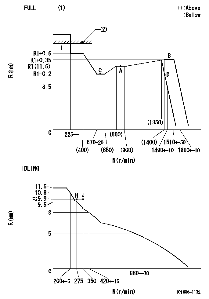
N:Pump speed
R:Rack position (mm)
(1)Torque cam stamping: T1
(2)RACK LIMIT
----------
T1=C92
----------
----------
T1=C92
----------
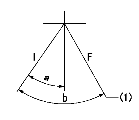
Speed control lever angle

F:Full speed
I:Idle
(1)Stopper bolt set position 'H'
----------
----------
a=18.5deg+-5deg b=(42deg)+-3deg
----------
----------
a=18.5deg+-5deg b=(42deg)+-3deg
Stop lever angle

N:Engine manufacturer's normal use
S:Stop the pump.
(1)Set the stopper bolt at speed = rated point and rack position = aa (non-injection rack position). Confirm non-injection.
(2)After setting the stopper bolt , confirm non-injection at pump speed bb. Rack position = cc (non-injection rack position).
(3)Rack position = approximately dd
(4)Free (at shipping)
----------
aa=(7)mm bb=275r/min cc=(8)mm dd=17.4mm
----------
a=38.5deg+-5deg b=(27deg) c=17deg+-5deg
----------
aa=(7)mm bb=275r/min cc=(8)mm dd=17.4mm
----------
a=38.5deg+-5deg b=(27deg) c=17deg+-5deg
0000001201
I:Idle
F:At operation, hold it in the full speed position.
(1)Rack position = aa, speed = bb.
----------
aa=8.5mm bb=1490r/min
----------
a=15deg+-5deg b=(36deg)+-3deg
----------
aa=8.5mm bb=1490r/min
----------
a=15deg+-5deg b=(36deg)+-3deg
0000001501 MICRO SWITCH
Adjustment of the micro-switch
Adjust the bolt to obtain the following lever position when the micro-switch is ON.
(1)Speed N1
(2)Rack position Ra
----------
N1=400+-5r/min Ra=9.7mm
----------
----------
N1=400+-5r/min Ra=9.7mm
----------
Timing setting

(1)Pump vertical direction
(2)Position of timer's tooth at No 1 cylinder's beginning of injection
(3)B.T.D.C.: aa
(4)-
----------
aa=12deg
----------
a=(1deg)
----------
aa=12deg
----------
a=(1deg)
Information:
Engine Description
Older 3408 and 3412 models may by precombustion chamber (PC) type engines. Newer 3408 and 3412 models are direct injection (DI) engines.A mechanical governor controls the fuel injection pump output to maintain the engine rpm selected by the operator. The fuel injection pump meters and pumps fuel under high pressure to a fuel injection nozzle for each cylinder. An automatic timing device advances or retards fuel injection to provide the best fuel injection timing over the full range of engine speed.The air/fuel ratio control, located on the governor, restricts the movement of the fuel rack, allowing only the proper amount of fuel to be injected into the cylinders during acceleration, to minimize exhaust smoke.These engines are available as turbocharged (T) or turbocharged and aftercooled (TA). Inlet air is filtered by an air cleaner before entering the engine cylinders. In turbocharged engines, the filtered inlet air is compressed by a turbocharger before entering the engine cylinders. The turbocharger is driven by the engine exhaust.There are four in-head valves (two inlet valves and two exhaust valves) for each cylinder. The camshaft actuates the rocker arms and the valves through mechanical lifters and push rods.The jacket water cooling system uses an expansion tank and a gear driven centrifugal water pump. The engine coolant is circulated by passing through the oil cooler first, then to the engine block and cylinder head. One water temperature regulator for each cylinder bank regulates engine coolant temperature by restricting coolant flow for quick engine warm-up. The regulator opens to allow free circulation of coolant after operating temperature has been reached.The watercooled exhaust manifolds, risers and turbochargers are designed to minimize radiated heat in the engine room.Lubrication of the engine is accomplished by a gear-type pump and bypass valves. The pump provides full pressure lubrication to the engine internal and external parts. The engine lubricating oil (both cooled and filtered) provides unrestricted flow to engine parts when oil viscosity is high or if the oil cooler is restricted or if the oil filter elements become plugged.The engines are available with SAE standard counterclockwise rotation (CCW when viewed from rear of engine). The engines can be equipped with either the SAE No.1 flywheel or the SAE No.0 flywheel to mate with various marine gears. Several marine gear manufacturers offer marine transmissions for the engines through local distributors.Engine Specifications
3408 Engine
3412 Engine
Have questions with 101606-1132?
Group cross 101606-1132 ZEXEL
Mitsubishi
101606-1132
ME076012
INJECTION-PUMP ASSEMBLY
6D15
6D15