Information injection-pump assembly
ZEXEL
101606-1131
1016061131

Rating:
Cross reference number
ZEXEL
101606-1131
1016061131
Zexel num
Bosch num
Firm num
Name
Calibration Data:
Adjustment conditions
Test oil
1404 Test oil ISO4113 or {SAEJ967d}
1404 Test oil ISO4113 or {SAEJ967d}
Test oil temperature
degC
40
40
45
Nozzle and nozzle holder
105780-8140
Bosch type code
EF8511/9A
Nozzle
105780-0000
Bosch type code
DN12SD12T
Nozzle holder
105780-2080
Bosch type code
EF8511/9
Opening pressure
MPa
17.2
Opening pressure
kgf/cm2
175
Injection pipe
Outer diameter - inner diameter - length (mm) mm 6-2-600
Outer diameter - inner diameter - length (mm) mm 6-2-600
Overflow valve
131424-5520
Overflow valve opening pressure
kPa
255
221
289
Overflow valve opening pressure
kgf/cm2
2.6
2.25
2.95
Tester oil delivery pressure
kPa
157
157
157
Tester oil delivery pressure
kgf/cm2
1.6
1.6
1.6
Direction of rotation (viewed from drive side)
Left L
Left L
Injection timing adjustment
Direction of rotation (viewed from drive side)
Left L
Left L
Injection order
1-5-3-6-
2-4
Pre-stroke
mm
3.6
3.55
3.65
Beginning of injection position
Governor side NO.1
Governor side NO.1
Difference between angles 1
Cal 1-5 deg. 60 59.5 60.5
Cal 1-5 deg. 60 59.5 60.5
Difference between angles 2
Cal 1-3 deg. 120 119.5 120.5
Cal 1-3 deg. 120 119.5 120.5
Difference between angles 3
Cal 1-6 deg. 180 179.5 180.5
Cal 1-6 deg. 180 179.5 180.5
Difference between angles 4
Cyl.1-2 deg. 240 239.5 240.5
Cyl.1-2 deg. 240 239.5 240.5
Difference between angles 5
Cal 1-4 deg. 300 299.5 300.5
Cal 1-4 deg. 300 299.5 300.5
Injection quantity adjustment
Adjusting point
-
Rack position
11
Pump speed
r/min
850
850
850
Each cylinder's injection qty
mm3/st.
60
58.1
61.9
Basic
*
Fixing the rack
*
Standard for adjustment of the maximum variation between cylinders
*
Injection quantity adjustment_02
Adjusting point
-
Rack position
10+-0.5
Pump speed
r/min
275
275
275
Each cylinder's injection qty
mm3/st.
10
8.9
11.1
Fixing the rack
*
Standard for adjustment of the maximum variation between cylinders
*
Remarks
Adjust only variation between cylinders; adjust governor according to governor specifications.
Adjust only variation between cylinders; adjust governor according to governor specifications.
Injection quantity adjustment_03
Adjusting point
A
Rack position
R1(11)
Pump speed
r/min
850
850
850
Average injection quantity
mm3/st.
60
59
61
Basic
*
Fixing the lever
*
Injection quantity adjustment_04
Adjusting point
B
Rack position
R1+0.6
Pump speed
r/min
1450
1450
1450
Average injection quantity
mm3/st.
80.5
78.5
82.5
Fixing the lever
*
Injection quantity adjustment_05
Adjusting point
I
Rack position
-
Pump speed
r/min
100
100
100
Average injection quantity
mm3/st.
80
75
85
Fixing the lever
*
Rack limit
*
Timer adjustment
Pump speed
r/min
1250--
Advance angle
deg.
0
0
0
Remarks
Start
Start
Timer adjustment_02
Pump speed
r/min
1200
Advance angle
deg.
0.5
Timer adjustment_03
Pump speed
r/min
1350
Advance angle
deg.
2.4
1.9
2.9
Timer adjustment_04
Pump speed
r/min
1500
Advance angle
deg.
5
4.5
5.5
Remarks
Finish
Finish
Test data Ex:
Governor adjustment
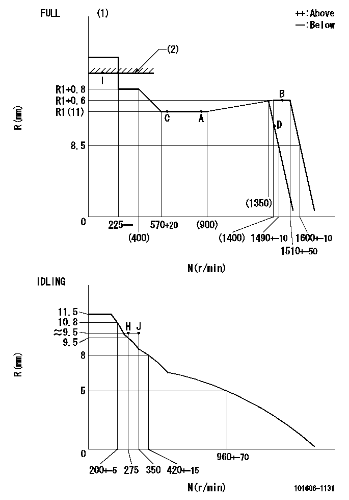
N:Pump speed
R:Rack position (mm)
(1)Torque cam stamping: T1
(2)RACK LIMIT
----------
T1=C69
----------
----------
T1=C69
----------
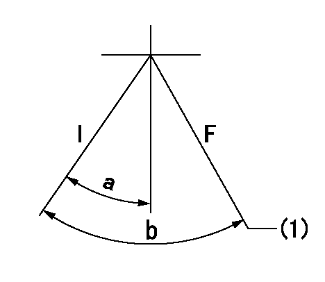
Speed control lever angle

F:Full speed
I:Idle
(1)Stopper bolt set position 'H'
----------
----------
a=18.5deg+-5deg b=(42deg)+-3deg
----------
----------
a=18.5deg+-5deg b=(42deg)+-3deg
Stop lever angle

N:Engine manufacturer's normal use
S:Stop the pump.
(1)Set the stopper bolt at speed = rated point and rack position = aa (non-injection rack position). Confirm non-injection.
(2)After setting the stopper bolt , confirm non-injection at pump speed bb. Rack position = cc (non-injection rack position).
(3)Rack position = approximately dd
(4)Free (at shipping)
----------
aa=(7)mm bb=275r/min cc=(8)mm dd=17.4mm
----------
a=38.5deg+-5deg b=(27deg) c=17deg+-5deg
----------
aa=(7)mm bb=275r/min cc=(8)mm dd=17.4mm
----------
a=38.5deg+-5deg b=(27deg) c=17deg+-5deg
0000001201
I:Idle
F:At operation, hold it in the full speed position.
(1)Rack position = aa, speed = bb.
----------
aa=8.5mm bb=1490r/min
----------
a=15deg+-5deg b=(36deg)+-3deg
----------
aa=8.5mm bb=1490r/min
----------
a=15deg+-5deg b=(36deg)+-3deg
0000001501 MICRO SWITCH
Adjustment of the micro-switch
Adjust the bolt to obtain the following lever position when the micro-switch is ON.
(1)Speed N1
(2)Rack position Ra
----------
N1=400+-5r/min Ra=9.2mm
----------
----------
N1=400+-5r/min Ra=9.2mm
----------
Timing setting

(1)Pump vertical direction
(2)Position of timer's tooth at No 1 cylinder's beginning of injection
(3)B.T.D.C.: aa
(4)-
----------
aa=12deg
----------
a=(1deg)
----------
aa=12deg
----------
a=(1deg)
Information:
Fire Extinguisher
Have a fire extinguisher available and know how to use it. Inspect and have it serviced as recommended on its instruction plate.Crushing or Cutting Prevention
Support equipment and attachments properly when working beneath them.Never attempt adjustments while the engine is running unless otherwise specified in this manual.Stay clear of all rotating and moving parts. Guards should be in place whenever maintenance is not being performed.Keep objects away from moving fan blades. They will throw or cut any object or tool that falls or is pushed into them.Wear protective glasses when striking objects to avoid injury to your eyes.Chips or other debris can fly off objects when struck. Make sure no one can be injured by flying debris before striking any object.Mounting and Dismounting
Do not climb on, or jump off the engine or stand on components which cannot support your weight. Use an adequate ladder. Always use steps and handholds when mounting and dismounting.Clean steps, handholds and areas of the engine you will be working on or around.Before Starting the Engine
Inspect engine for potential hazards.Be sure all protective guards and covers are installed if an engine must be started to make adjustments or checks. To help prevent an accident caused by parts in rotation, work carefully around them.Do not disable or bypass automatic shutoff circuits. They are provided to prevent personal injury and engine damage.Never start an engine with the governor linkage disconnected.Make provisions for shutting off the air or fuel supply to stop the engine if there is an overspeed on start-up after performing repair or maintenance to the engine.See the Maintenance section of this manual for adjustment, or the Service Manual for repairs.Engine Starting
DO NOT start the engine or move any of the controls if there is a warning tag attached to the controls. Check with the person who attached the tag before starting.Make sure no one is working on, or close to the engine or engine driven components before starting it. Always make an inspection of the engine before and after starting.Start the engine only from the operator's station. Never short across the starter terminals or the batteries as this could bypass the engine neutral-start system as well as damage the electrical system.Always start the engine according to the required Engine Starting procedure described in this manual to prevent major engine component damage and personal injury.Make sure the engine is equipped with a lighting system as required by conditions.Make sure all lights are working properly.Check the jacket water and oil temperature gauges frequently during the operation of jacket water and/or lube oil heaters to ensure proper operation.Diesel engine exhaust contains products of combustion which may be harmful to your health. Always start and operate the engine in a well-ventilated area and, if in an enclosed area, vent the exhaust to the outside.Ether
Ether is poisonous and flammable.Inhaling ether vapors or repeated contact of ether with skin can cause personal injury.Do not smoke while changing ether cylinders.Use ether only in well ventilated areas.Use ether with care to avoid