Information injection-pump assembly
ZEXEL
101606-1120
1016061120
Rating:
Cross reference number
ZEXEL
101606-1120
1016061120
Zexel num
Bosch num
Firm num
Name
Calibration Data:
Adjustment conditions
Test oil
1404 Test oil ISO4113 or {SAEJ967d}
1404 Test oil ISO4113 or {SAEJ967d}
Test oil temperature
degC
40
40
45
Nozzle and nozzle holder
105780-8140
Bosch type code
EF8511/9A
Nozzle
105780-0000
Bosch type code
DN12SD12T
Nozzle holder
105780-2080
Bosch type code
EF8511/9
Opening pressure
MPa
17.2
Opening pressure
kgf/cm2
175
Injection pipe
Outer diameter - inner diameter - length (mm) mm 6-2-600
Outer diameter - inner diameter - length (mm) mm 6-2-600
Overflow valve
131424-5520
Overflow valve opening pressure
kPa
255
221
289
Overflow valve opening pressure
kgf/cm2
2.6
2.25
2.95
Tester oil delivery pressure
kPa
157
157
157
Tester oil delivery pressure
kgf/cm2
1.6
1.6
1.6
Direction of rotation (viewed from drive side)
Left L
Left L
Injection timing adjustment
Direction of rotation (viewed from drive side)
Left L
Left L
Injection order
1-5-3-6-
2-4
Pre-stroke
mm
3.6
3.55
3.65
Beginning of injection position
Governor side NO.1
Governor side NO.1
Difference between angles 1
Cal 1-5 deg. 60 59.5 60.5
Cal 1-5 deg. 60 59.5 60.5
Difference between angles 2
Cal 1-3 deg. 120 119.5 120.5
Cal 1-3 deg. 120 119.5 120.5
Difference between angles 3
Cal 1-6 deg. 180 179.5 180.5
Cal 1-6 deg. 180 179.5 180.5
Difference between angles 4
Cyl.1-2 deg. 240 239.5 240.5
Cyl.1-2 deg. 240 239.5 240.5
Difference between angles 5
Cal 1-4 deg. 300 299.5 300.5
Cal 1-4 deg. 300 299.5 300.5
Injection quantity adjustment
Adjusting point
-
Rack position
10.8
Pump speed
r/min
850
850
850
Each cylinder's injection qty
mm3/st.
60
58.1
61.9
Basic
*
Fixing the rack
*
Standard for adjustment of the maximum variation between cylinders
*
Injection quantity adjustment_02
Adjusting point
H
Rack position
9.5+-0.5
Pump speed
r/min
275
275
275
Each cylinder's injection qty
mm3/st.
9.3
8.2
10.4
Fixing the rack
*
Standard for adjustment of the maximum variation between cylinders
*
Injection quantity adjustment_03
Adjusting point
A
Rack position
R1(10.8)
Pump speed
r/min
850
850
850
Average injection quantity
mm3/st.
60
59
61
Basic
*
Fixing the lever
*
Injection quantity adjustment_04
Adjusting point
B
Rack position
R1+0.6
Pump speed
r/min
1450
1450
1450
Average injection quantity
mm3/st.
80.5
78.5
82.5
Fixing the lever
*
Injection quantity adjustment_05
Adjusting point
I
Rack position
-
Pump speed
r/min
100
100
100
Average injection quantity
mm3/st.
80
75
85
Fixing the lever
*
Rack limit
*
Timer adjustment
Pump speed
r/min
1250--
Advance angle
deg.
0
0
0
Remarks
Start
Start
Timer adjustment_02
Pump speed
r/min
1200
Advance angle
deg.
0.5
Timer adjustment_03
Pump speed
r/min
1350
Advance angle
deg.
2.4
1.9
2.9
Timer adjustment_04
Pump speed
r/min
1500
Advance angle
deg.
5
4.5
5.5
Remarks
Finish
Finish
Test data Ex:
Governor adjustment
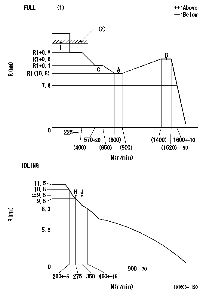
N:Pump speed
R:Rack position (mm)
(1)Torque cam stamping: T1
(2)RACK LIMIT
----------
T1=C19
----------
----------
T1=C19
----------
Speed control lever angle

F:Full speed
I:Idle
(1)Stopper bolt set position 'H'
----------
----------
a=10deg+-5deg b=(46deg)+-3deg
----------
----------
a=10deg+-5deg b=(46deg)+-3deg
Stop lever angle

N:Engine manufacturer's normal use
S:Stop the pump.
(1)Set the stopper bolt at pump speed = aa and rack position = bb (non-injection rack position). Confirm non-injection.
(2)After setting the stopper bolt, confirm non-injection at speed cc. Rack position = dd (non-injection rack position).
(3)Rack position = approximately ee.
(4)Free (at shipping)
----------
aa=1550r/min bb=(7.1)mm cc=275r/min dd=(8.8)mm ee=17.4mm
----------
a=38.5deg+-5deg b=(27deg) c=17deg+-5deg
----------
aa=1550r/min bb=(7.1)mm cc=275r/min dd=(8.8)mm ee=17.4mm
----------
a=38.5deg+-5deg b=(27deg) c=17deg+-5deg
0000001501 MICRO SWITCH
Adjustment of the micro-switch
Adjust the bolt to obtain the following lever position when the micro-switch is ON.
(1)Speed N1
(2)Rack position Ra
----------
N1=400+-5r/min Ra=9.2mm
----------
----------
N1=400+-5r/min Ra=9.2mm
----------
Timing setting

(1)Pump vertical direction
(2)Position of timer's tooth at No 1 cylinder's beginning of injection
(3)B.T.D.C.: aa
(4)-
----------
aa=12deg
----------
a=(1deg)
----------
aa=12deg
----------
a=(1deg)
Information:
Alternator and Fan Drive Belts
Inspect/Adjust/Replace
Your engine will be equipped with a water pump belt and a pair of belts for the fan drive and alternator. Inspect the condition and adjustment of alternator and fan drive belts. Inspect all drive belts and replace if they show any signs of wear.Check and adjust the belt tension to minimize belt slippage. If belts are too loose, they vibrate enough to cause unnecessary wear on the belts and pulleys. If belts are too tight, unnecessary stresses are placed upon the pulley bearings and belts which might shorten the life of both.To Adjust Drive Belt
The alternator is used for tension adjustment. Correctly adjusted belts will deflect approximately 9 to 15 mm (3/8 to 5/8 inch). If new belt(s) are installed, check belt adjustment again after 30 minutes of operation.To adjust the belt tension, loosen the alternator bolts and slide the alternator in the desired direction to increase or decrease the belt tension. 1. To adjust the alternator drive belt, loosen mounting bolt (1) and the adjusting bracket bolt (2).2. Move the alternator in or out as required to obtain the correct adjustment. Tighten the bolts (1) and (2). Do not overtighten.3. If new belts are installed, check belt adjustment again after 30 minutes of engine operation.To Adjust Water Pump Belt
1. To adjust the water pump drive belt, loosen mounting bolt and bracket bolt.2. Move water pump idler pulley in or out as required to obtain the correct adjustment.3. To make the correct adjustment, use the square hole in the mounting bracket or bolt to apply tension.4. Tighten bolts. Do not overtighten. The water pump belt is not used to drive any other accessories. Excessive tightening can damage the water pump bearings or shaft.5. If a new belt is installed, check the belt adjustment again after 30 minutes of engine operation at rated speed.Fan Drive Bearing
Lubricate
Lubricate one fitting with Caterpillar 2S3230 SPG grease. Refer to the Lubrication Specifications section in this Manual for the proper lubricating grease to be used.Inspect the fan drive pulley assembly. It should be difficult to detect movement of the shaft in the bearing. If the shaft is loose in the bearings, an inspection of the internal components should be made.The bearing end play should be 0.03 to 0.23 mm (.001 to .009 inch). The radial play should be no greater than 0.13 mm (.005 inch). Fan Clutch-For emergency operation or electrical override, use one M6 x 1 cap screw inserted in fan spider clearance holes to allow continuous operation of fan. Have fan clutch repaired at next stop.
Do NOT operate engine with this condition for long periods of time because an engine over cooling problem (low operating temperatures) will cause sludge formation and excessive carbon build-up on critical engine components.
If the assembly should require disassembly, refer to the Service Manual for the procedure.Battery
Check the following at least every 6 months, and more often if conditions require.Tighten Terminals
* Clean the top of the batteries with a clean cloth. Loosen and