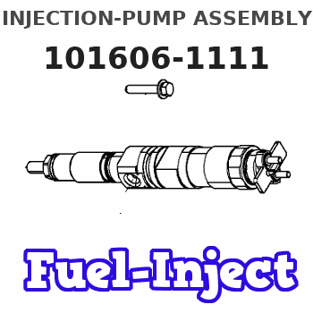
Information injection-pump assembly
ZEXEL
101606-1111
1016061111
Rating:
Cross reference number
ZEXEL
101606-1111
1016061111
Zexel num
Bosch num
Firm num
Name
Calibration Data:
Adjustment conditions
Test oil
1404 Test oil ISO4113 or {SAEJ967d}
1404 Test oil ISO4113 or {SAEJ967d}
Test oil temperature
degC
40
40
45
Nozzle and nozzle holder
105780-8140
Bosch type code
EF8511/9A
Nozzle
105780-0000
Bosch type code
DN12SD12T
Nozzle holder
105780-2080
Bosch type code
EF8511/9
Opening pressure
MPa
17.2
Opening pressure
kgf/cm2
175
Injection pipe
Outer diameter - inner diameter - length (mm) mm 6-2-600
Outer diameter - inner diameter - length (mm) mm 6-2-600
Overflow valve
131424-5520
Overflow valve opening pressure
kPa
255
221
289
Overflow valve opening pressure
kgf/cm2
2.6
2.25
2.95
Tester oil delivery pressure
kPa
157
157
157
Tester oil delivery pressure
kgf/cm2
1.6
1.6
1.6
Direction of rotation (viewed from drive side)
Left L
Left L
Injection timing adjustment
Direction of rotation (viewed from drive side)
Left L
Left L
Injection order
1-5-3-6-
2-4
Pre-stroke
mm
3.6
3.55
3.65
Beginning of injection position
Governor side NO.1
Governor side NO.1
Difference between angles 1
Cal 1-5 deg. 60 59.5 60.5
Cal 1-5 deg. 60 59.5 60.5
Difference between angles 2
Cal 1-3 deg. 120 119.5 120.5
Cal 1-3 deg. 120 119.5 120.5
Difference between angles 3
Cal 1-6 deg. 180 179.5 180.5
Cal 1-6 deg. 180 179.5 180.5
Difference between angles 4
Cyl.1-2 deg. 240 239.5 240.5
Cyl.1-2 deg. 240 239.5 240.5
Difference between angles 5
Cal 1-4 deg. 300 299.5 300.5
Cal 1-4 deg. 300 299.5 300.5
Injection quantity adjustment
Adjusting point
-
Rack position
11.3
Pump speed
r/min
850
850
850
Each cylinder's injection qty
mm3/st.
65.4
63.5
67.3
Basic
*
Fixing the rack
*
Standard for adjustment of the maximum variation between cylinders
*
Injection quantity adjustment_02
Adjusting point
H
Rack position
9.9+-0.5
Pump speed
r/min
275
275
275
Each cylinder's injection qty
mm3/st.
9.2
8.1
10.3
Fixing the rack
*
Standard for adjustment of the maximum variation between cylinders
*
Injection quantity adjustment_03
Adjusting point
A
Rack position
R1(11.3)
Pump speed
r/min
850
850
850
Average injection quantity
mm3/st.
65.4
64.4
66.4
Basic
*
Fixing the lever
*
Injection quantity adjustment_04
Adjusting point
B
Rack position
R1+0.6
Pump speed
r/min
1450
1450
1450
Average injection quantity
mm3/st.
81.2
77.2
85.2
Fixing the lever
*
Injection quantity adjustment_05
Adjusting point
C
Rack position
R1(11.3)
Pump speed
r/min
600
600
600
Average injection quantity
mm3/st.
49.5
45.5
53.5
Fixing the lever
*
Injection quantity adjustment_06
Adjusting point
I
Rack position
-
Pump speed
r/min
100
100
100
Average injection quantity
mm3/st.
80
75
85
Fixing the lever
*
Rack limit
*
Timer adjustment
Pump speed
r/min
1250--
Advance angle
deg.
0
0
0
Remarks
Start
Start
Timer adjustment_02
Pump speed
r/min
1200
Advance angle
deg.
0.5
Timer adjustment_03
Pump speed
r/min
1350
Advance angle
deg.
2.4
1.9
2.9
Timer adjustment_04
Pump speed
r/min
1500
Advance angle
deg.
5
4.5
5.5
Remarks
Finish
Finish
Test data Ex:
Governor adjustment
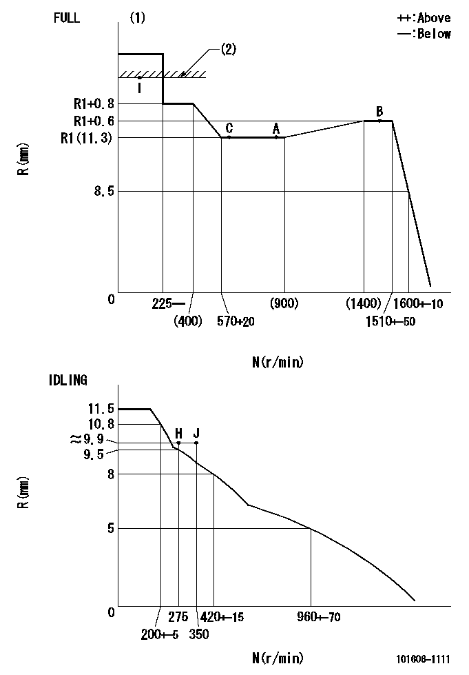
N:Pump speed
R:Rack position (mm)
(1)Torque cam stamping: T1
(2)RACK LIMIT
----------
T1=C69
----------
----------
T1=C69
----------
Speed control lever angle

F:Full speed
I:Idle
(1)Stopper bolt set position 'H'
----------
----------
a=18.5deg+-5deg b=(42deg)+-3deg
----------
----------
a=18.5deg+-5deg b=(42deg)+-3deg
Stop lever angle

N:Engine manufacturer's normal use
S:Stop the pump.
(1)Set the stopper bolt at speed = rated point and rack position = aa (non-injection rack position). Confirm non-injection.
(2)After setting the stopper bolt , confirm non-injection at pump speed bb. Rack position = cc (non-injection rack position).
(3)Rack position = approximately dd
(4)Free (at shipping)
----------
aa=7mm bb=275r/min cc=(8)mm dd=17.4mm
----------
a=38.5deg+-5deg b=(27deg) c=17deg+-5deg
----------
aa=7mm bb=275r/min cc=(8)mm dd=17.4mm
----------
a=38.5deg+-5deg b=(27deg) c=17deg+-5deg
0000001501 MICRO SWITCH
Adjustment of the micro-switch
Adjust the bolt to obtain the following lever position when the micro-switch is ON.
(1)Speed N1
(2)Rack position Ra
----------
N1=400+-5r/min Ra=9.7mm
----------
----------
N1=400+-5r/min Ra=9.7mm
----------
Timing setting

(1)Pump vertical direction
(2)Position of timer's tooth at No 1 cylinder's beginning of injection
(3)B.T.D.C.: aa
(4)-
----------
aa=12deg
----------
a=(1deg)
----------
aa=12deg
----------
a=(1deg)
Information:
Lubricant Viscosity Recommendations
The proper SAE grade of oil to select is determined by the minimum outside temperature at which the engine will be started and the maximum outside temperature in which the engine will be operating. This recommendation is to ensure the correct viscosity is used until the next oil change. Engine start-up at lower than specified ambient temperature requires caution. Start-up at very low ambient temperatures may require a jacket water heater, auxiliary oil heaters or other methods to increase the engine crankcase and surrounding temperatures. When operating below -20°C (-4°F) refer to Caterpillar for information.The use of multi-viscosity oils is preferred because of full protection through a wider temperature range. See chart for recommended viscosity and temperature range. To determine if the oil in the crankcase will flow in cold weather, remove the oil dipstick before starting. If the oil will flow off, the oil is fluid enough to circulate properly.Lubricant Viscosity Chart
Refill Capacities
Engine Crankcase Oil Capacity
The crankcase refill capacities reflect the engine crankcase capacity plus on-engine oil filter change. If equipped with an auxiliary oil filter system, consult the oil filter system manufacturer for information.Total Cooling System Capacity
The Total Cooling System capacity will vary, depending on the engine model (3114 or 3116), radiator system size and capacity provided by truck/vehicle manufacturer. In order to properly maintain the cooling system, Total Cooling System capacity must be known. The chart below is left blank and should be filled in by the customer to determine the Total Cooling System Capacity for his engine and application.Add 0.25 liter (0.5 U.S. pint) of Caterpillar liquid supplemental coolant additive (Conditioner) for every 30 liter (8 U.S. gallon) of cooling system capacity to maintain the cooling system at Every 250 Service Hours.